Use Model-Based Design to Build a Battery Management System
The example outlines The MathWorks® tools, tips, and processes that you and your teams can employ during these development stages, while also highlighting best practices and tools for collaborative design such as:
MATLAB® and Simulink® projects for file management.
Requirements management with the Requirements Editor (Requirements Toolbox).
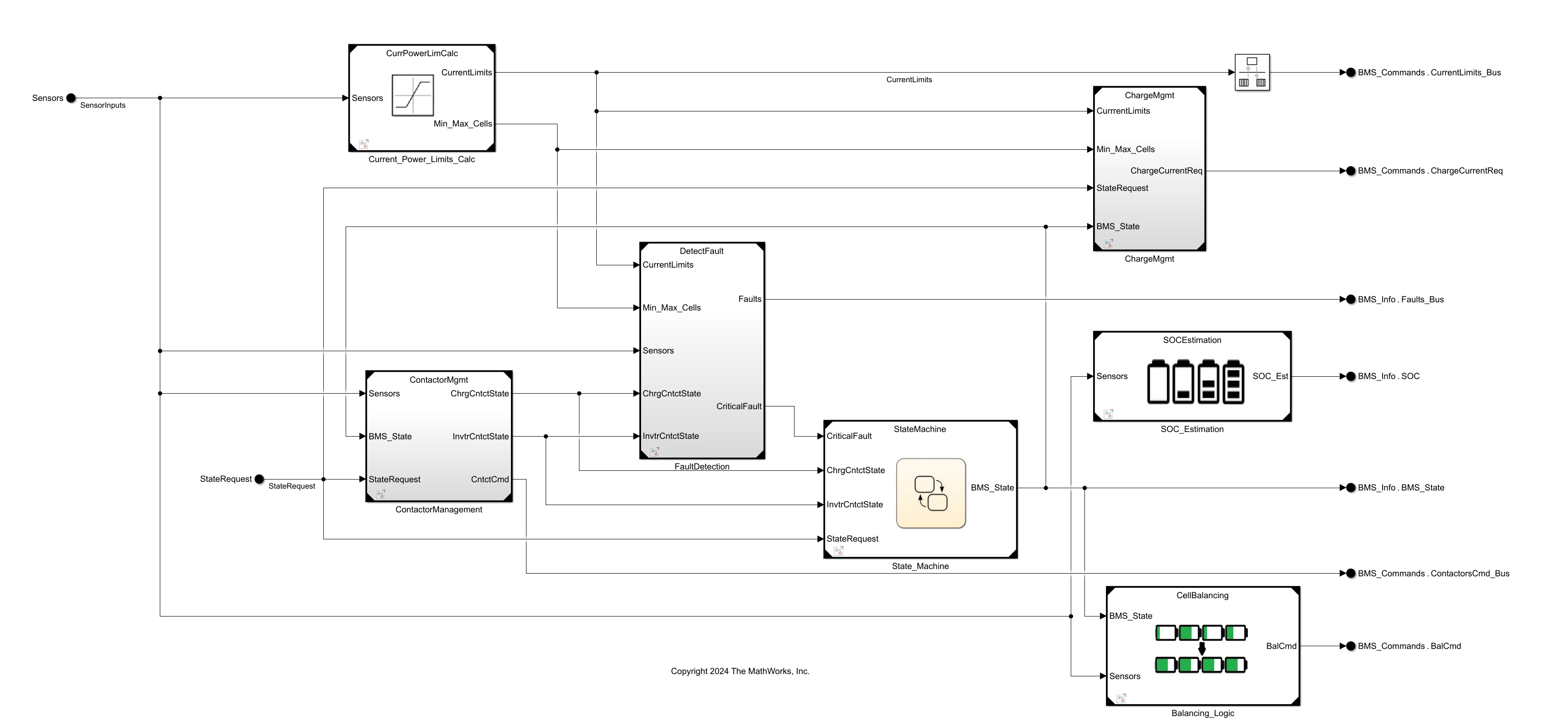
System architecture and functionality.
Model decomposition.
Data management and data decomposition in a model.
Getting started with unit-level, subsystem-level, and system-level workflows.
Handling multiple parallel simulations.
Improving simulation performance.
Upgrading tool versions for support across releases.
This project presents the resulting battery management system (BMS) developed using a model-based design workflow. It utilizes a Nickel-Manganese-Cobalt (NMC) cell with a capacity of 27 Ah.
Battery Management System Workflow Steps
Click on each box in the flow chart to follow the steps for building a battery management system.
Battery Management System Project
Click the open button to load the project to your working folder.
See Also
Topics
- Requirements Editor (Requirements Toolbox)
- Project Management
- Scale Up Simulink Models