Signal Editor
R2026bDisplay, create, edit, and switch interchangeable scenarios
Signal Editor block block

To add a block to a model, double-click the canvas and start typing the block name. Then, select the block from the list.
Libraries:
Simulink /
Sources
Description
The Signal Editor block displays, creates, and edits interchangeable scenarios, which contain signals. Signals can be:
MATLAB®
timeseriesobjects.timeseriesobjects cannot have emptyDataproperties.timetableobjects.timetableobjects cannot represent multiple variables.Structure of MATLAB
timeseriesortimetableobjects.Two-dimensional matrices.
The block creates one port for each signal.
To create and edit scenarios and the signals contained in the scenarios, click
Open Signal Editor ( ). You can also use the Signal Editor
block to switch scenarios in and out of models.
). You can also use the Signal Editor
block to switch scenarios in and out of models.
The Signal Editor block supports MAT files that contain signals as one
or more scalar Simulink.SimulationData.Dataset objects.
While there is no specific maximum number of signals the Signal Editor block supports, a higher number of signals increases the possibility that block performance slows.
Create and Edit Scenarios and Signals
To create and edit scenarios and the signals contained in them, open the Signal
Editor tool by clicking . The Signal Editor tool enables you to easily
manipulate signals in these ways:
Create and edit multiple signals in multiple data sets. By default, the Signal Editor creates timeseries format data.
Use signal notations to create more complicated signals using MATLAB expressions. You can use the Author and Insert dialog box or manually enter simple MATLAB expressions in the tabular area.
Use existing scenarios to get existing data sets for which you can edit and create signals.
Create and edit multidimensional signals.
For more information on the Signal Editor tool, see Create and Edit Signal Data.
Programmatic Interactions
To programmatically get the total number of scenarios and signals in the
Signal Editor block, use the get_param
function with the NumberOfScenarios and
NumberOfSignals parameters, respectively. These read-only
parameters contain the values as character vectors. To convert these values to
doubles, use the str2double function.
To programmatically enable the Signal Editor block to label output
signal lines, set PreserveSignalName to 'on'
(default) with the set_param function.
set_param(gcb,'PreserveSignalName','on')
For more information on programmatic interactions, see Parameters and Replace Programmatic Use of signalbuilder.
Import and Export
The Signal Editor supports custom file types, such as Microsoft® Excel®, by letting you:
Edit signals imported from registered custom file types. For more information, see Import Custom File Type.
Export signals from Signal Editor to your registered custom file types. For more information, see Export Signals to Custom Registered File Types.
Migrating from Signal Builder Blocks
You can port Signal Builder block configurations to the
Signal Editor block using the
signalBuilderToSignalEditor function. For more information,
see Replace Signal Builder Block with Signal Editor Block and Migrate from Signal Builder Block to Signal Editor Block.
Fast Restart
The Signal Editor block supports fast restart. With fast restart enabled, you can still:
Change the active scenario.
Change the active signal.
While you can change the active signal, you cannot edit the signal properties in the block.
Open the Signal Editor and edit data.
Examples
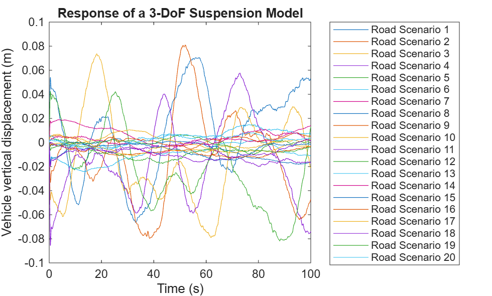
Run Test-Case Sweep Using Parallel Simulations
Run multiple Simulink® simulations corresponding to different test cases using batchsim and Parallel Computing Toolbox™. The batchsim function offloads simulations to a compute cluster, freeing up your local machine so you can continue working while the batch job is processing. While parsim is useful for running parallel simulations on local resources, batchsim is useful for running a large number of computationally expensive simulations. If you do not have Parallel Computing Toolbox, the simulations in this example will run serially.
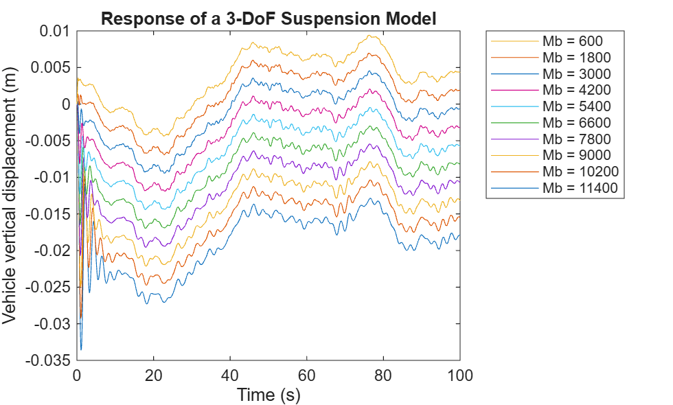
Run Parameter Sweep in Rapid Accelerator Mode Using Parallel Simulations
Run multiple accelerated simulations in parallel by using parsim and Parallel Computing Toolbox™. Run Parameter Sweep Using Parallel Simulations shows how to use multiple cores of your host machine to run independent simulations while varying a parameter. In this example, use rapid accelerator mode to speed up multiple simulations even further. If you do not have Parallel Computing Toolbox or MATLAB Parallel Server™, the simulations in this example run serially.
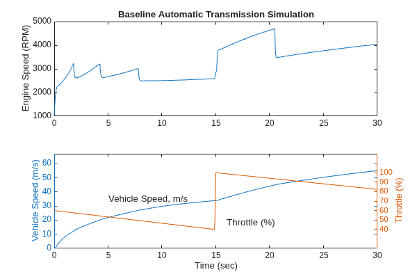
Model an Automatic Transmission Controller
Model an automotive drivetrain using Simulink®. In this model, a Stateflow® chart implements the transmission control logic and integrates directly with the Simulink model, combining control logic and drivetrain dynamics in a clear and intuitive structure.
Limitations
The Signal Editor block does not support:
Function-calls
Ground signals
The Signal Editor block supports dynamic strings. It does not support strings with maximum length. In addition, strings in the Signal Editor block cannot output:
Non-scalar MATLAB strings.
String data that contains missing values.
String data that contains non-ASCII characters.
Ports
Output Arguments
Parameters
To open the Signal Editor, click Open Signal
Editor (). The Signal Editor opens
with all the active scenario signals plotted.
To see the signal data changes from the Signal Editor tool, click the Save button in the Signal Editor tool toolstrip. This button is disabled when you change a parameter in the dialog box.
Dependencies
To enable this button, click the Apply button.
Programmatic Use
To open the Signal Editor, use the signalEditor
function. For more information. see Signal Editor.
Data set file, specified as character vector, containing one or more
scalar Simulink.SimulationData.Dataset objects. Do not use
a filename from one locale in a different locale. When using the block on
multiple platforms, consider specifying just the MAT filename and having the
MAT file be on the MATLAB path.
To create a MAT file, click . This button opens the Signal
Editor, which lets you create and edit scenario MAT files.
Programmatic Use
Block Parameter:
Filename |
| Type: character vector |
| Values: character vector |
Default:
'untitled.mat' |
Active scenario, specified as a character vector. You can switch the active scenario as necessary.
If you create this block by using the
signalBuilderToSignalEditor function or the
Check model for Signal Builder blocks Upgrade
Advisor check to convert a Signal Builder block to a
Signal Editor block, the active scenario name is the data
set variable name in the MAT file. However, if you pause on this parameter,
the original Signal Builder group name is displayed.
Dependencies
To enable this parameter, ensure that the specified MAT file exists.
Programmatic Use
Block Parameter:
ActiveScenario |
| Type: character vector | numeric |
| Values: character vector | index value |
Default:
'Scenario' |
Signal property source, specified as:
Signal data in MAT file— Use signal properties from the MAT file specified in File name. If the signal does not have unit or interpolation properties, the signal property defaults to the Signal Editor block dialog box setting. These properties include:Dialog parameters— Use signal properties from the block dialog box.
When this parameter is set to Signal data in MAT
file, the Apply signal properties to all
scenarios and Apply signal properties to all
signals parameters must be cleared and cannot be
changed.
Dependencies
To enable this parameter, ensure that the specified MAT file exists.
Programmatic Use
Block Parameter:
'SignalPropertySource' |
| Type: character vector |
Values: Dialog
parameters | Signal data in MAT
file |
Default: 'Signal data
in MAT file' |
Signal to configure, specified as a signal name. This signal is considered the active signal.
This parameter has no effect when the Apply signal properties to all signals parameter is selected.
Dependencies
To enable this parameter, ensure that the specified MAT file exists.
Programmatic Use
Block Parameter:
ActiveSignal |
| Type: character vector | numeric |
| Values: character vector | index vector |
Default: 'Signal
1' |
Do not use the set_param function to set
ActiveSignal in combination with another
name-value argument of the Signal Editor block.
Option to apply the specified signal properties.
on— Apply the specified signal properties to the active signal in all scenarios.off— Apply signal properties only in the current active scenario.
If the Apply signal properties to all signals parameter is also selected, the block applies the signal properties to all signals in all scenarios.
Dependencies
To enable this parameter, set the Use properties
from parameter to Dialog
parameters.
Programmatic Use
Block Parameter:
ApplySigPropsToAllScenarios |
| Type: character vector |
Values: 'off' |
'on' |
Default:
'on' |
Option to apply the specified signal properties.
on— Apply the specified signal properties to all the signals in the active scenario. There is no concept of an active signal.off— Do not apply signal property to all signals.
If the Apply signal properties to all scenarios parameter is also selected, the block applies the signal properties to all signals in all scenarios.
Dependencies
To enable this parameter, set the Use properties
from parameter to Dialog
parameters.
Programmatic Use
Block Parameter:
ApplySigPropsToAllSignals |
| Type: character vector |
Values: 'off' |
'on' |
Default:
'off' |
To configure a signal as a bus, select this parameter.
Select this parameter only if the active signal is a MATLAB structure whose fields are the same as an existing bus object, or create a new matching bus object. If you select this parameter for an active signal that is not a MATLAB structure, simulation returns an error.
Dependencies
To enable this parameter, ensure that the specified MAT file exists.
Programmatic Use
Block Parameter:
IsBus |
| Type: character vector |
Values: 'off' |
'on' |
Default:
'off' |
Select or enter the bus object name. To edit the bus object or create a bus object using the Data Type Assistant, click >>. The active signal must be a MATLAB structure whose fields are the same as this bus object.
Dependencies
To enable this parameter, select Output a bus signal.
Programmatic Use
Block Parameter:
OutputBusObjectStr |
| Type: character vector |
| Values: bus object name |
Default: 'Bus:
BusObject' |
Specify the bus object name. If you do not have a bus object, create one by clicking Edit, which opens the Type Editor. For more information, see Create Simulink Bus Objects.
Dependencies
To enable this parameter, select Output a bus signal and click >>.
Physical unit of the signal, specified as an allowed unit. To specify a unit, begin typing in the text box. As you type, the parameter displays potential matching units. For more information, see Unit Specification in Simulink Models. For a list of supported units, see Allowed Unit Systems.
To constrain the unit system, click the link to the right of the parameter:
If a Unit System Configuration block exists in the component, its dialog box opens. Use that dialog box to specify allowed and disallowed unit systems for the component.
If a Unit System Configuration block does not exist in the component, the model Configuration Parameters dialog box displays. Use that dialog box to specify allowed and disallowed unit systems for the model.
If the Apply signal properties to all scenarios parameter is also selected, the block applies the signal properties to all signals in all scenarios.
Dependencies
To enable this parameter, set the Use properties
from parameter to Dialog
parameters.
Programmatic Use
Block Parameter:
Unit |
| Type: character vector |
Values:
'inherit' | supported physical unit |
Default:
'inherit' |
Time interval between samples, specified in seconds.
Dependencies
To enable this parameter, the MAT file specified in File name must exist.
Programmatic Use
Block Parameter:
SampleTime |
| Type: character vector |
Values: -1 |
sample time in seconds |
Default:
'0' |
Linearly interpolate data at time hits for which no corresponding workspace data exist.
on— Linearly interpolate at time hits for which no corresponding workspace data exist.Note
If the Signal Editor block is the source for a new Simulink® Test™ or Simulink Design Verifier™ test harness model, the Interpolate data parameter is off by default.
off— The current output equals the output at the most recent time for which data exists.
The Signal Editor block interpolates by using the two corresponding workspace samples.
For
doubledata, the Signal Editor block linearly interpolates the value by using the two corresponding samples.For
Booleandata, the Signal Editor block usesfalsefor the first half of the time between two time values andtruefor the second half.For a built-in data type other than
doubleorBoolean, the Signal Editor block:Upcasts the data to
doublePerforms linear interpolation (as described for
doubledata)Downcasts the interpolated value to the original data type
When you load enumerated, fixed-point, variable-size signal, or string data, clear the Interpolate data parameter.
The block uses the value of the last known data point as the value of time hits that occur after the last known data point.
To determine the block output after the last time hit for which data is available, combine the settings of these parameters:
Interpolate data
Form output after final data value by
For details, see Form output after final data value by.
In rapid accelerator mode, the Signal Editor block does not
support int64 and uint64 data types
when the Interpolate data parameter is
selected.
If the Apply signal properties to all scenarios parameter is also selected, the block applies the signal properties to all signals in all scenarios.
Dependencies
To enable this parameter, set the Use properties
from parameter to Dialog
parameters.
Programmatic Use
Block Parameter:
Interpolate |
| Type: character vector |
Values: 'off' |
'on' |
Default:
'on' |
If you select Enable zero-crossing detection, the Signal Editor block detects a zero crossing when the input array contains multiple entries for the same time value. For example, suppose that the block loads this input data.
time: 0 1 2 2 3 signal: 2 3 4 5 6
At time 2, a zero crossing occurs because of the
discontinuity in the input data. For more information, see Zero-Crossing Detection.
When you load input data for a bus, the Signal Editor block detects zero crossings for all leaf bus elements.
This block supports zero-crossing detection only in simulations that use a variable-step solver. When you use a fixed-step solver for simulation, the software does not detect or locate zero crossings for this block.
Dependencies
To enable this parameter, ensure that the specified MAT file exists.
Programmatic Use
Block Parameter:
ZeroCross |
| Type: character vector |
Values: 'off' |
'on' |
Default:
'off' |
To determine the block output after the last time hit for which workspace data is available, combine the settings of these parameters:
Interpolate data
Form output after final data value by
This table lists the block output, based on the values of the two options.
| Setting for Form Output After Final Data Value By | Setting for Interpolate Data | Block Output After Final Data |
|---|---|---|
|
On |
Extrapolated from final data value |
|
Off |
Error | |
|
On |
Zero |
|
Off |
Zero | |
|
On |
Final value from workspace |
|
Off |
Final value from workspace |
For example, the block uses the last two known data points to extrapolate data points that occur after the last known point if you:
Select Interpolate data.
Set Form output after final data value by to
Extrapolation.
Dependencies
To enable this parameter, ensure that the specified MAT file exists.
Programmatic Use
Block Parameter:
OutputAfterFinalValue |
| Type: character vector |
Values: 'Setting to
zero' | 'Extrapolation' | 'Holding final
value' |
Default: 'Setting to
zero' |
Block Characteristics
Data Types |
|
Direct Feedthrough |
|
Multidimensional Signals |
|
Variable-Size Signals |
|
Zero-Crossing Detection |
|
Extended Capabilities
Version History
Introduced in R2017bThe Open Signal Editor button in the Signal
Editor block now opens a version of the Signal
Editor tool that is synchronized with the Signal Editor
block. In releases prior to R2026a, all instances of the Signal Editor
tool had the same characteristics. For more information, see Differences Between the Signal Editors.
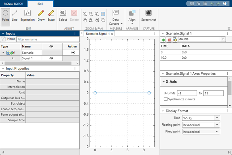
The block version of the Signal Editor tool has these changes:
When you click Open Signal Editor, the Signal Editor tool now opens populated with the active scenario. The active plot shows the last signal in the scenario.
A new Active column in the hierarchy shows the active scenario for the block. To change the active scenario, click the associated button.
New input properties support the corresponding block parameters.
Signal Editor Block Signal Editor Interface Output as bus object
Bus object
Enable zero-crossing detection
Form output after final data value by
Sample time
Sample time Note
The Interpolate data and Unit parameters of the Signal Editor tool are only reflected in the Signal Editor block when the block parameter Use properties from is set to
Signal data in MAT file.To change the active scenario in the Signal Editor tool, click the associated button in the hierarchy Active column, and then click Save. Closing the tool updates the Signal Editor block.
Block parameters become read-only when you open the Signal Editor tool. To change control from the Signal Editor tool to the Signal Editor block, close the Signal Editor tool.
To see parameter changes for an active signal from the Signal Editor block in the associated Signal Editor tool, click the active signal in the signal hierarchy.
See Also
Functions
Tools
Checks
Topics
- Signal Basics
- Create and Edit Signal Data
- Create Simulink Bus Objects
- Load Data with Interchangeable Scenarios
- Migrate from Signal Builder Block to Signal Editor Block
- Signal Editor Block
- How to Create Freehand Input Signals in the Signal Editor in Simulink
- How to Import and Export Excel Files in Signal Editor

