Eye Measurement
Libraries:
Mixed-Signal Blockset /
Utilities
SerDes Toolbox /
Utilities
Signal Integrity Toolbox /
Utilities
Description
The Eye Measurement block generates eye pattern from time-domain waveform data and calculates metrics from the generated pattern.
Examples
This example shows how to produce eye diagrams and related metrics for sampled data systems in Simulink.
Set Up Eye Measurement Block
Open the model eyeMeasurementInDFECDRExampleModel
attached with this example. The model was originally created in the SerDes Designer app and then exported to Simulink®. For more information, see Design SerDes System and Export IBIS-AMI Model (SerDes Toolbox).
model = "eyeMeasurementInDFECDRExampleModel";
open_system(model);
In the eyeMeasurementInDFECDRExampleModel
model, double-click on the Rx
subsystem. Then right-click the DFECDR and select Look under mask to enter the DFECDR
subsystem. Add an Eye Measurement block.
Note The Eye Measurement block is not supported for IBIS-AMI model generation. Remove the Eye Measurement block before exporting the model to IBIS-AMI.
Double-click on the Eye Measurement block to open its dialog.
Set the Configuration tab parameters to match the signal:
Set Enable threshold input port to
on
Set Modulation to
Modulation
Set Enable clock input port to
on
Set Amplitude range to
[-0.2, 0.2]
Set Hold off time to
IgnoreBits
and its unit toUI
Set Symbol time (s) to
SymbolTime
Set Sample time (s) to
SampleInterval
phaseOffset = 0.7;
Modulation
, IgnoreBits
, SymbolTime
, and SampleInterval
are model properties controlled by the Configuration block in the top level of the model.
In the Eye Mask tab:
Set Eye mask type to
Rectangular
Set W1 (UI) to
0.2
Set H to
0.1
In the Metric Setup tab:
Set Store results in base workspace to
on
Set Result variable name to
eyeResults
This saves the metrics to the base workspace in the variable named eyeResults
once the simulation ends.
Apply the changes.
Connect Eye Measurement Block to DFECDR
Connect the data input of the Eye Measurement block to the output signal from the DFECDR. Add a Bus Selector block. Connect the input of the bus selector to the ClkAMI output port on the DFECDR. Use the Bus Selector to select the signal clockTime
from the bus.
Connect the output port from the bus selector to the clock input port on the Eye Measurement block. Connect the PAM_Thresholds
signal from the DFECDR to the thresholds input to the Eye Measurement block.
open_system(model + "/Rx/DFECDR", "force");
Run the simulation and confirm that the eye opening is centered, the correct number of unit intervals is visible, and that the dynamic range of the signal is fully within the diagram.
sim(model);
Export Metric Results
Once the simulation is complete, find the metric results in the base workspace.
disp(eyeResults);
Metric Position Unit SER Extrapolation Results _________________ ________ _________ _____ _____________ ____________ "Eye Height" {[ 0]} "Seconds" 1e-05 "None" {1×1 struct} "Best Eye Height" {[NaN]} "NaN" 1e-05 "None" {1×1 struct} "Eye Mask Margin" {[NaN]} "NaN" 1e-05 "none" {1×1 struct}
To retrieve the width and height margins, select the last element in the results column of the table, and from that structure retrieve the field named Margin.
eyeResults.Results{end}.Margin
ans = -0.0035 -0.0255
This example shows how to produce eye diagrams and related metrics for specific signals in a SerDes system using the Eye Measurement block.
Set Up Constants
This example compares eye openings at three different signals in the model:
The input to the receiver
The output of the CTLE
The output of the DFE
Open the model eyeMeasurementExampleModel_1Eye
attached with this example. The model was originally created in the SerDes Designer app and then exported to Simulink®. For more information, see Design SerDes System and Export IBIS-AMI Model (SerDes Toolbox).
model = "eyeMeasurementExampleModel_1Eye";
open_system(model);
The Eye Measurement block does not have a phase detector or CDR, but the eye opening must be centered in the diagram for metric calculations to succeed. Use a manual phase offset to center the eye opening.
phaseOffset = 0.7; % UI
Measure Eye at DFE Output
In the eyeMeasurementExampleModel_1Eye
model, double-click on the Rx
subsystem. Add an Eye Measurement block.
Note Eye Measurement block is not supported for IBIS-AMI model generation. Remove the Eye Measurement block(s) before exporting the model to IBIS-AMI.
Double-click on the Eye Measurement block to open the Block Parameters dialog box.
Set the Configuration tab parameters to match the signal:
Set Enable threshold input port to
off
Set Modulation to
Modulation
Set Symbol thresholds to
0
Set Enable clock input port to
off
Set Phase offset to
phaseOffset
and its unit toUI
Set Amplitude range to
[-0.2, 0.2]
Set Hold off time to
IgnoreBits
and its unit toUI
Set Symbol time (s) to
SymbolTime
Set Sample time (s) to
SampleInterval
Modulation
, IgnoreBits
, SymbolTime
, and SampleInterval
are model properties controlled by the Configuration block in the top level of the model.
Apply the changes.
Connect the data input of the Eye Measurement block to the output signal from the DFECDR
. Name the Eye Measurement block Eye 3: DFE
.
open_system(model + "/Rx");
Run the simulation and confirm that the eye opening is centered, the correct number of unit intervals is visible, and that the dynamic range of the signal is fully within the diagram.
sim(model);
Warning: Warning from 'eyeMeasurementExampleModel_1Eye/Rx/Eye 3: DFE': Number of eye openings at center (3) was not the expected number of eye openings (1), metrics may be incorrect. Ensure 'Modulation' is correct, open the eye further, or manually center the eye using 'PhaseOffset'.
Measure Eye at CTLE Output
Copy the Eye Measurement block and paste the copy into the model. Rename the copy to Eye 2: CTLE
. Connect its data input to the output of the CTLE
.
Measure Eye at Receiver Input
Paste another copy of the Eye Measurement block and rename it to Eye 1: Channel
. Connect its data input to the input to the CTLE
.
bdclose(model); model = "eyeMeasurementExampleModel_3Eye"; load_system(model); open_system(model + "/Rx");
Running the simulation as-is produces errors when the Eye Measurement block connected to the CTLE
input attempts to calculate its metrics because its eye is closed. To avoid this, double click on the block to open its dialog and change the following parameters:
In the Metric Setup tab, click on each metric and then click Remove Selected Metrics. You can shift-click to select multiple metrics.
Additionally, to fit the data in the eye diagram, in the Configuration tab set Amplitude range to [-0.5, 0.5]
.
Apply the changes.
Run the simulation. There will be a warning because Eye 1: Channel
is measuring a closed eye. This is expected, because that eye is measured at the output of the channel, before the receiver. The subsequent eyes (Eye 2: CTLE
and Eye 3: DFE
) are open due to RX equalization performed by the CLTE and DFE.
sim(model);
Warning: Warning from 'eyeMeasurementExampleModel_3Eye/Rx/Eye 1: Channel': Number of eye openings at center (0) was not the expected number of eye openings (1), metrics may be incorrect. Ensure 'Modulation' is correct, open the eye further, or manually center the eye using 'PhaseOffset'. Warning: Warning from 'eyeMeasurementExampleModel_3Eye/Rx/Eye 2: CTLE': Number of eye openings at center (3) was not the expected number of eye openings (1), metrics may be incorrect. Ensure 'Modulation' is correct, open the eye further, or manually center the eye using 'PhaseOffset'. Warning: Warning from 'eyeMeasurementExampleModel_3Eye/Rx/Eye 3: DFE': Number of eye openings at center (3) was not the expected number of eye openings (1), metrics may be incorrect. Ensure 'Modulation' is correct, open the eye further, or manually center the eye using 'PhaseOffset'.
Limitations
Eye Measurement block does not support rapid accelerator mode.
Ports
Input
Input data used to construct the eye pattern, specified as a scalar.
Data Types: double
Sampling clock signal for input data, specified as a scalar. Windows for the eye pattern are centered on the clock edges.
If you are using clock times at the clock port, new clock times must be within 1 UI of the current simulation time. Clock times should occur in the center of the corresponding eye opening.
Dependencies
To enable this port, select the Enable clock input port in the Configuration tab.
Data Types: double
Symbol threshold(s), used to separate symbols when building the eye diagram. If you provide this information, it increases the robustness of the PAMn metrics.
If the data at the thresholds port is a vector, the same vector is used across all time points during measurements. If the data at the thresholds port is a matrix, the block uses one vector for each time point.
Dependencies
To enable this port, select the Enable threshold input port in the Configuration tab.
Data Types: double
Parameters
To edit block parameters interactively, use the Property Inspector. From the Simulink® Toolstrip, on the Simulation tab, in the Prepare gallery, select Property Inspector.
Configuration
Select to enable the threshold input port. By default, this port is enabled.
Number of symbol levels expected in the eye diagram, specified as a nonnegative integer scalar.
Programmatic Use
Block parameter:
Modulation |
Type: character vector |
Values: nonnegative integer scalar |
Default:
2 |
Select to enable the clock input port. By default, this port is enabled.
Determine how to sample waveform clock signals:
Rising
— Sample the data waveform at the rising edge of the clock waveform.Falling
— Sample the data waveform at the falling edge of the clock waveform.Both
— Sample the data waveform at both rising and falling edges of the clock waveform.Times
— Sample the data waveform at the time values specified by the clock signal.
Programmatic Use
Block parameter:
ClockType |
Type: character vector |
Values:
Rising | Falling |
Both | Times |
Default:
Rising |
Edge detection threshold for waveform clocks, specified as a real scalar.
Dependencies
To enable this parameter, set the Enable clock input port
option as on and set the Clock type as
Rising
, Falling
, or
Both
.
Programmatic Use
Block parameter:
ClockThreshold |
Type: character vector |
Values: real scalar |
Default:
0 |
Represent how data is captured by the recovered clock from the system perspective.
Clocked
— The data is captured at the input to the decision latch using the clock from the output of the clock recovery circuit.Ideal
— The data and clock are captured using an ideal reference clock source.Convolved
— The data eye and clock PDF captured in normal mode are convolved together to present an eye and clock that look as though the simulation had been run in clocked mode.
For more information, see Clock Modes.
Note
If you set the Enable clock input port option as off,
Clock mode is set to Ideal
and you
cannot change it.
Programmatic Use
Block parameter:
ClockMode |
Type: character vector |
Values:
Clocked | Ideal |
Convolved |
Default:
Clocked |
Delay between the clock edge and the timing origin, specified as a nonnegative real scalar in seconds, samples, or UI.
Note
Phase offset delay must be causal.
Programmatic Use
Block parameter:
PhaseOffset |
Type: character vector |
Values: nonnegative real scalar |
Default:
0 |
The width of the eye diagram in symbols, specified as a scalar.
Programmatic Use
Block parameter:
SymbolsperDiagram |
Type: character vector |
Values: scalar |
Default:
2 |
Minimum and maximum amplitudes contained in the eye diagram, specified as a two-element vector.
Programmatic Use
Block parameter:
AmplitudeRange |
Type: character vector |
Values: two-element vector |
Default:
[] |
Number of amplitude bins in the eye diagram, specified as a positive integer scalar.
Programmatic Use
Block parameter:
AmplitudeBins |
Type: character vector |
Values: positive integer scalar |
Default:
257 |
Number of time bins in the eye diagram, specified as a positive integer scalar.
Programmatic Use
Block parameter:
TimeBins |
Type: character vector |
Values: positive integer scalar |
Default:
256 |
Delays measurement analysis to avoid corruption by transients, specified as a nonnegative real scalar in seconds, samples, or UI.
Programmatic Use
Block parameter:
HoldOffTime |
Type: character vector |
Values: nonnegative real scalar |
Default:
0 |
Time for one symbol, specified as a positive real scalar.
Note
Symbol time must be evenly divisible by Sample time.
Programmatic Use
Block parameter:
SymbolTime |
Type: character vector |
Values: positive real scalar |
Default:
16e-9 |
Time for one sample, specified as a positive real scalar.
If Sample time is specified as a 2- element vector, it represents the fixed-step discrete sample time in Simulink.
If Sample time is specified as a scalar, it represents the sample interval used in the SerDes Toolbox™.
Note
Symbol time must be evenly divisible by Sample time.
Programmatic Use
Block parameter:
SampleTime |
Type: character vector |
Values: two-element vector | scalar |
Default:
[1e-9, 0] |
Metric Setup
Click to add new eye diagram metric to calculate. You can define which metric to calculate at what point, the symbol error rate, and the extrapolation method.
Click to remove selected eye diagram metrics to focus on the area of interest.
Select to store the metric calculation result to the base workspace at the end of simulation.
Name of the metrics variable that stores measurement results in the base workspace.
Programmatic Use
Block parameter:
MetricsVariableName |
Type: character vector |
Values: string |
Default:
ans |
Click to export the simulation results to a file to save for later use.
Click to export the simulation results to the base workspace.
Eye Mask
Shape of the eye mask for the mask margin measurement. For more information, see
eyeMask
(Mixed-Signal Blockset).
The width of the rectangle or diamond eye masks or the width at the center of the hexagon eye mask, specified as a positive real scalar.
Dependencies
To enable this parameter, set Eye mask type to
Rectangle
, Diamond
, or
Hexagon
.
Programmatic Use
Block parameter:
W1 |
Type: character vector |
Values: positive real scalar |
Default:
0.2 |
The width at the top and bottom of the hexagon eye mask, specified as a positive real scalar.
Dependencies
To enable this parameter, set Eye mask type to
Hexagon
.
Programmatic Use
Block parameter:
W2 |
Type: character vector |
Values: positive real scalar |
Default:
0.1 |
The height of the rectangle, diamond or hexagon eye masks, specified as a positive real scalar.
Dependencies
To enable this parameter, set Eye mask type to
Rectangle
, Diamond
, or
Hexagon
.
Programmatic Use
Block parameter:
H |
Type: character vector |
Values: positive real scalar |
Default:
0.1 |
Define the position of origin of the shape of the mask in the eye diagram. You can position it at the clock, or for the best eye height or width.
Dependencies
To enable this parameter, set Eye mask type to
Rectangle
, Diamond
, or
Hexagon
.
Programmatic Use
Block parameter:
PositionMaskInEye |
Type: character vector |
Values:
At clock | For best height
margin | For best width margin |
Default:
At clock |
Define a custom eye mask from an eye mask object.
Dependencies
To enable this parameter, set Eye mask type to
Custom
.
Programmatic Use
Block parameter:
CustomEyeMask |
Type: character vector |
Values: object |
Default:
[] |
Symbol error rate (SER) at which the block measures the eye mask margin, specified as a nonnegative real scalar in the range [0,1].
Dependencies
To enable this parameter, set Eye mask type to
Rectangle
, Diamond
,
Hexagon
, or Custom
.
Programmatic Use
Block parameter:
MarginSER |
Type: character vector |
Values: nonnegative real scalar in the range [0,1] |
Default:
1e-5 |
Extrapolation method to generate eye contours used for measuring eye margins. The block extrapolates eye diagram to a specified SER using interpolation between adjacent bins. For more information, see Extrapolation (Mixed-Signal Blockset).
Note
This functionality requires a license to Signal Integrity Toolbox™, Optimization Toolbox™, or Curve Fitting Toolbox™. The license requirements are listed according to the order of performance, where Signal Integrity Toolbox provides fastest calculation.
Dependencies
To enable this parameter, set Eye mask type to
Rectangle
, Diamond
,
Hexagon
, or Custom
.
Programmatic Use
Block parameter:
MarginExtrapolation |
Type: character vector |
Values:
none | dualdirac |
gaussian | linear |
spline | pchip |
makima |
Default:
none |
Name of the mask variable to export the mask to the base workspace.
Programmatic Use
Block parameter:
MaskVariableName |
Type: character vector |
Values: string |
Default:
ans |
Click to export the mask to a file to save for later use.
Click to export the mask to the base workspace.
Plot Setup
Select to automatically show the simulation results as plots at the end of simulation. You can define which type of plot to generate, including the eye, clock, and bathtub.
Define how the plots are grouped together.
Click to add new plot to show.
Click to remove selected plots to focus on the area of interest.
Click to show the plots.
More About
The Eye Measurement block extrapolates its 2-D histogram to a specified symbol error rate whenever it generates bathtub curves or eye contours.
During extrapolation method, the block pre-processes the data, one symbol at a time on only a 1-D slice of the said symbol. The block extrapolates the eye diagram at the specified SER value using the interpolation between the adjacent bins.
The block provides five interpolation methods (none
,
linear
, spline
,
pchip
, and makima
) and two
extrapolation methods (gaussian
and
dualdirac
) to extrapolate data.
This image shows how the block uses interpolation methods to extrapolate data.
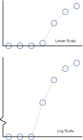
The blue dots represent the cumulative sum of the eye diagram going outward from the center of the eye. The blue dot at the x-axis value zero represents the eye opening. The dotted red line shows the interpolated samples.
The log scale image is used to create the bathtub curves. The discontinuity at the logarithmic scale is to show the zero x-axis value. The linear scale image shows how the cumulative sum of the 1-D slice of the eye looks on the same scale as the slice itself..
For example, the none
extrapolation method uses a previous
neighbor interpolation of the cumulative sum an eye slice. For horizontal eye slices, the
extrapolation uses the timing origins. For vertical eye slices, the extrapolation uses the
symbol thresholds.
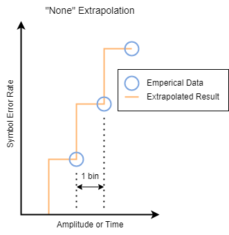
When moving outward from the center of the eye, it is a previous neighbor interpolation. When moving across the eye from one side to the other, it appears as a next neighbor interpolation that switches to a previous neighbor interpolation as you pass the center of the eye. This way, the result for a symbol error rate is a conservative estimate from the perspective of the eye opening, based on the data.
On the other hand, the dualdirac
extrapolation algorithm
first fits the Dual-Dirac PDF to a column of the split histogram. Then it uses those
coefficients to calculate the inverse Dual-Dirac CDF for the specified SER(s). It is only
applicable to systems with an exponential impulse response whose time constant is on the
order of the time for one symbol, or less. The algorithm is also significantly slower that
the None extrapolation method.
This table summarizes the different extrapolation methods the block supports.
Method | Description | Comments |
---|---|---|
none | Uses previous neighbor interpolation of each eye slice to find the SER values. The interpolated value at any query point is the value at the previous sample grid point. |
|
dualdirac | Fits a Dual-Dirac model to each slice of the eye, then uses the fitted model to find the SER values. |
|
gaussian | Uses the Gaussian defined by the sample mean and sample standard deviation of each eye slice to find the SER values. |
|
linear | Uses linear interpolation of each eye slice to find the SER values. The interpolated value at any query point is based on linear interpolation of the values at neighboring grid points in each respective dimension. |
|
spline | Uses natural spline interpolation of the cumulative sum out from the center of each eye slice to find SER values. |
|
pchip | Uses shape-preserving piecewise cubic interpolation of each eye slice to find the SER values. The interpolated value at any query point is based on a shape-preserving piecewise cubic interpolation of the values at neighboring grid points. |
|
makima | Uses modified Akima cubic Hermite interpolation of each eye slice to find the SER values. The interpolated value at a query point is based on any piecewise function of polynomials with degree at most three. The Akima formula is modified to avoid overshoots. |
|
Version History
Introduced in R2024aChoose from different extrapolation methods to observe the trend in eye metrics as you change system parameters to satisfy your requirements.
See Also
eyeDiagramSI
(Mixed-Signal Blockset) | eyeContour
(Mixed-Signal Blockset) | eyeMask
(Mixed-Signal Blockset)
Topics
- Choose Extrapolation Method Based on Application (Mixed-Signal Blockset)
MATLAB Command
You clicked a link that corresponds to this MATLAB command:
Run the command by entering it in the MATLAB Command Window. Web browsers do not support MATLAB commands.
Select a Web Site
Choose a web site to get translated content where available and see local events and offers. Based on your location, we recommend that you select: .
You can also select a web site from the following list
How to Get Best Site Performance
Select the China site (in Chinese or English) for best site performance. Other MathWorks country sites are not optimized for visits from your location.
Americas
- América Latina (Español)
- Canada (English)
- United States (English)
Europe
- Belgium (English)
- Denmark (English)
- Deutschland (Deutsch)
- España (Español)
- Finland (English)
- France (Français)
- Ireland (English)
- Italia (Italiano)
- Luxembourg (English)
- Netherlands (English)
- Norway (English)
- Österreich (Deutsch)
- Portugal (English)
- Sweden (English)
- Switzerland
- United Kingdom (English)