Analog Channel
R2026bConstruct loss model from channel loss metric or impulse response
Analog Channel block
To add a block to a model, double-click the canvas and start typing the block name. Then, select the block from the list.
Libraries:
SerDes Toolbox /
Utilities
Description
The Analog Channel block constructs a loss model using a channel loss metric or an impulse response from another source in a SerDes Toolbox™ model. Analog model inputs are only used for IBIS file construction when using impulse response. For more information, see Analog Channel Loss in SerDes System.
Ports
Input
Input signal, specified as a waveform.
Data Types: double
Output
Modified output data that includes the effect of a lossy printed circuit board transmission line model according to the method outlined in [1].
Data Types: double
Parameters
Channel Model
Source of channel model.
Select
Loss modelto model the analog channel from a loss model.Select
Impulse responseto model the analog channel from an impulse response.
Programmatic Use
Block parameter:
ChannelType |
| Type: character vector |
Values:
Loss model | Impulse
response |
Default:
Loss model |
Frequency for the desired channel loss, specified as a positive real scalar in hertz. It corresponds to the Nyquist frequency of the system.
Dependencies
This parameter is only available when Loss model is
selected as Channel model.
Programmatic Use
Block parameter:
TargetFrequency |
| Type: character vector |
| Values: positive real scalar |
Default:
20e9 |
Data Types: double
Channel loss at the target frequency, specified as a nonnegative real scalar in dB.
Dependencies
This parameter is only available when Loss model is
selected as Channel model.
Programmatic Use
Block parameter:
Loss |
| Type: character vector |
| Values: nonnegative real scalar |
Default:
8 |
Data Types: double
Characteristic impedance of the channel, specified as a positive real scalar in ohms. Impedance (Ohms) depends on the setting of Signaling in the Configuration tab in the SerDes Designer app or in the Configuration block.
If Signaling is set to
Differential, the default value of Impedance (Ohms) is100.If Signaling is set to
Single-ended, the default value of Impedance (Ohms) is50.
Dependencies
This parameter is only available when Loss model is
selected as Channel model.
Programmatic Use
Block parameter:
Zc |
| Type: character vector |
| Values: positive real scalar |
Default:
100 |
Data Types: double
User provided impulse response, specified as a unitless matrix. Impulse response is used to construct a channel loss model from the user-defined impulse response of the system.
You can use user specified impulse response to define your own crosstalk. If you decide to include crosstalk from your custom impulse response, you can specify up to six crosstalk stimuli as new columns in the impulse response.
Dependencies
This parameter is only available when Impulse
response is selected as Channel model
Programmatic Use
Block parameter:
ImpulseResponse |
| Type: character vector |
| Values: matrix |
Default:
[zeros(1,63),1/SampleInterval,zeros(1,192)] |
Data Types: double
Sample interval of the user provided impulse response, specified as a positive real scalar in seconds.
Programmatic Use
Block parameter:
ImpulseSampleInterval |
| Type: character vector |
| Values: positive real scalar |
Default:
6.25e-12 |
Data Types: double
Click to plot the impulse, step, and pulse responses of the analog channel. You must apply any changes you made to the analog channel before plotting the responses.
Click to generate the channel impulse response by combining an S-parameter model with the characteristics impedance of transmitter and receiver. This opens the S-Parameter Fitter app where you can import the S-parameter Touchstone file.
Analog Model
Single-ended impedance of the transmitter analog model, specified as a nonnegative real scalar in ohms.
Programmatic Use
Block parameter:
TxR |
| Type: character vector |
| Values: nonnegative real scalar |
Default:
50 |
Data Types: double
Capacitance of the transmitter analog model, specified as a nonnegative real scalar in farads.
Programmatic Use
Block parameter:
TxC |
| Type: character vector |
| Values: nonnegative real scalar |
Default:
100e-15 |
Data Types: double
Single-ended impedance of the receiver analog model, specified as a nonnegative real scalar in ohms.
Programmatic Use
Block parameter:
RxR |
| Type: character vector |
| Values: nonnegative real scalar |
Default:
50 |
Data Types: double
Capacitance of the receiver analog model, specified as a nonnegative real scalar in farads.
Programmatic Use
Block parameter:
RxC |
| Type: character vector |
| Values: nonnegative real scalar |
Default:
200e-15 |
Data Types: double
20%−80% rise time of the stimulus input to transmitter analog model, specified as a positive real scalar in seconds.
Programmatic Use
Block parameter:
RiseTime |
| Type: character vector |
| Values: positive real scalar |
Default:
10e-12 |
Data Types: double
Peak-to-peak voltage at the input of transmitter analog model, specified as a positive real scalar in volts.
Programmatic Use
Block parameter:
VoltageSwingIdeal |
| Type: character vector |
| Values: positive real scalar |
Default:
1 |
Data Types: double
Crosstalk
Select to include crosstalk in the simulation. By default, this option is deselected.
You can add up to 50 crosstalk aggressors and their individual stimulus settings as additional impulse response columns to the impulse response of the Channel Model tab. The block displays the crosstalk stimulus parameters as a table in the Crosstalk tab. You can customize the symbol time, delay, modulation and PRBS order or port of individual crosstalk aggressors.
Note
Adding more than six crosstalk aggressors requires a license for Signal Integrity Toolbox™.
Select to include bidirectional links in SerDes Simulink models. By default, this option is deselected.
If you select the Include Bi-Directional parameter, the crosstalk aggressor table in the Crosstalk tab contains a column for S22 input port with mutual exclusion to create the bidirectional link. You must provide the impulse responses for the bidirectional link using the Impulse response parameter in the Channel Model tab.
More About
ICN is a frequency domain metric where the crosstalk is multiplied by a weighting function and then numerically integrated from 50 MHz to the baud rate (fb). If there are multiple aggressors, their power are summed together before combining with the weighting function.
The time domain signal does not excite all frequencies evenly. The power spectral density (PSD) of a baseband time domain excitation follows a sinc-squared type response. The weighting function mimics the excitation of the PSD and shapes the PSD by including the effects of the receiver bandwidth and the transmitter rise time.
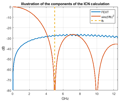
The total ICN is calculated by root-sum-squaring the FEXT ICN and NEXT ICN values together.
Algorithms
The impact felt on a victim line from a far end crosstalk aggressor is proportional to the rate of change of the aggressor waveform [2]. So, you can estimate the shape of a FEXT time domain signal with the derivative of the through response lossy impulse response.
where, kFEXT is a scale factor that scales the IFEXT(t) so that it has user specified ICN value.
To calculate the ICN of the signal, transform the signal to frequency domain using Fourier transform.
The magnitude of the scale factor kFEXT is: ,
where is the integrated crosstalk noise operator.
The sign of kFEXT is negative since in typical transmission lines in inhomogeneous dielectrics, the inducting coupling is generally greater than capacitive coupling. As a result, the forward crosstalk pulse has the opposite magnitude from the magnitude of the aggressor signal.
To calculate the near end crosstalk, note that the frequency domain NEXT response is similar in shape (not in magnitude) to the victim's return loss (S11 or S11).
Then the scale factor kNEXT is:
And the time domain NEXT signal is derived from the inverse Fourier transform.
References
[1] IEEE 802.3bj-2014. "IEEE Standard for Ethernet Amendment 2: Physical Layer Specifications and Management Parameters for 100 Gb/s Operation Over Backplanes and Copper Cables." URL: https://standards.ieee.org/standard/802_3bj-2014.html.
[2] Stephen Hall and Howard Heck. Advanced Signal Integrity for High-Speed Digital Designs. Hoboken, NJ: Wiley Press, 2009.
Version History
Introduced in R2019aDesign bidirectional links in the SerDes Simulink models.
You can instantiate multiple Analog Channel blocks in a SerDes system Simulink model to design redriver workflow.
MATLAB Command
You clicked a link that corresponds to this MATLAB command:
Run the command by entering it in the MATLAB Command Window. Web browsers do not support MATLAB commands.
Select a Web Site
Choose a web site to get translated content where available and see local events and offers. Based on your location, we recommend that you select: .
You can also select a web site from the following list
How to Get Best Site Performance
Select the China site (in Chinese or English) for best site performance. Other MathWorks country sites are not optimized for visits from your location.
Americas
- América Latina (Español)
- Canada (English)
- United States (English)
Europe
- Belgium (English)
- Denmark (English)
- Deutschland (Deutsch)
- España (Español)
- Finland (English)
- France (Français)
- Ireland (English)
- Italia (Italiano)
- Luxembourg (English)
- Netherlands (English)
- Norway (English)
- Österreich (Deutsch)
- Portugal (English)
- Sweden (English)
- Switzerland
- United Kingdom (English)