Couple Two Spinning Inertias with a Simple Gear
In this example, you couple two spinning inertias. In the first coupling, the inertias spin with the same angular velocity along a single shaft (driveline axis). Then the inertias spin at different velocities as they spin along two shafts and are coupled by a gear. Finally, the inertias are coupled by a gear and actuated by an external torque, so that they spin at different rates and experience different torques. For each model, the example uses basic Simscape™ mechanical and Simscape Driveline™ blocks, such as Inertia, Simple Gear, and Solver Configuration.
Modeling Two Spinning Inertias
Create the first version of the simplest, nontrivial driveline model, two inertias spinning together along the same axis. Open the Simscape Driveline, Simscape, and Simulink® block libraries and a new Simulink model window.
Drag and drop two Inertia, two Ideal Rotational Motion Sensor, two Mechanical Rotational Reference, and two PS-Simulink Converter blocks into the model window.
From the Simscape Utilities library, drag a Solver Configuration block. Every topologically distinct driveline block diagram requires exactly one instance of this block.
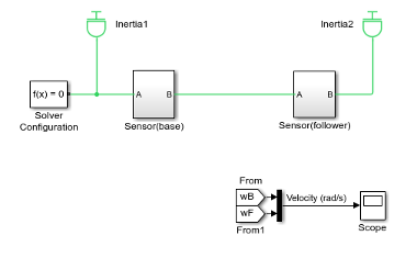
From the Simulink library, drag and drop a Scope, a Mux, and two pairs of Goto and From blocks. Connect the blocks as shown in the following figures. The sensor subsystems are arranged hierarchically.
Model with Two Spinning Inertias
Sensor Subsystem
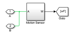
Motion Sensor Subsystem

At the start of the simulation, because there is no damping, the inertias rotate at the initial velocity that you specify. The connection line between the two Inertia blocks requires them to have the same rotational velocity. To specify the initial rotational velocity, open each Inertia block. In the Variables tab, select the Rotational velocity check box and set the Value parameter to
piradians/second (rad/s).Open the Scope block and start the simulation. The two angular velocities are constant at 3.14 radians/second.

Coupling Two Spinning Inertias with a Simple Gear
Modify the model you created by coupling the two spinning inertias with a simple, ideal gear with a fixed gear ratio.
From the Simscape Driveline block library, drag and drop a Simple Gear block into your model. Open the block. Change the default follower-base gear ratio value to
1. Change the Output shaft rotates menu to In same direction as input shaft and click OK. The simple gear then represents two gear wheels rotating together at the same rate in the same direction, with one wheel inside the other. Connect the blocks as shown in the following figure.Model with Two Spinning Inertias Coupled by a Gear
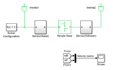
Leave the initial angular velocities at
piin the Inertia blocks.Open the Scope and start the simulation. The two angular velocities are constant at 3.14 radians/second for both Inertias.
Change the Output shaft rotates menu back to In opposite direction to input shaft. The simple gear then becomes two wheels rotating together in opposite directions, with the two wheels meshed on their respective outer surfaces. Change initial velocity in Inertia2 to
-pi.Restart the simulation. The two angular velocities are 3.14 and –3.14 radians/second for Inertia1 and Inertia2, respectively. The second angular velocity is the same, but with opposite sign, because the two bodies are spinning in opposite directions.
Change the Output shaft rotates menu again to In same direction as input shaft.
Torque-Actuating Two Coupled, Spinning Inertias
In the final version of the simple gear model, you actuate the inertias with an
external torque instead of starting them with fixed initial angular velocities. The
external torque varies sinusoidally. You can find a completed version of this model
in the SimpleGearExample model.
From the Simscape Foundation library, copy an Ideal Torque Source and two Ideal Torque Sensor blocks, plus a Simulink-PS Converter block and another Mechanical Rotational Reference block. From the Simulink library, drag and drop a Sine Wave block and two more pairs of Goto and From blocks.
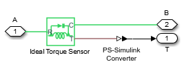
Connect the blocks as shown in the following figures. The Torque Sensor subsystems are arranged in parallel with the Motion Sensor subsystems inside the Sensor subsystem blocks. Set the initial velocities of both Inertias to zero. Change the default follower-base gear ratio value to
2. Modify the Scope block to add another axis for measuring the torques. Connect the other blocks as shown.Model with Two Spinning Inertias Coupled by a Gear and Actuated with Torque

Updated Sensor Subsystem
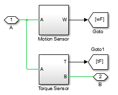
Torque Sensor Subsystem
Open the Scope block and start the simulation.
The measured torques and angular velocities vary sinusoidally. As in the preceding models, the angular velocity of Inertia2 is half that of Inertia1. The torque in the second (follower) shaft is twice that in the first, as required by the laws of gear coupling.
For the Simple Gear block, change the Output shaft rotates menu to In opposite direction to input shaft and restart the simulation. The same angular velocities and torques result, except that the values associated with Inertia2 and the second shaft are negative because the second body and second shaft are spinning in opposite directions.
Sensing and Actuating Motion and Torque
The mechanical sensor and source blocks that you use in the preceding models illustrate their dual nature. They act as driveline components themselves, but also let you inject and extract physical signals associated with motion and torque, including the appropriate physical units. You can use these physical signals with other blocks in the Simscape physical modeling environment, or convert them to dimensionless Simulink signals for use in the nonphysical part of your model. Both sensor and source blocks have pairs of mechanical ports and are connected either in series with or across physical connection lines.
Mechanical sensor and source blocks have both mechanical conserving ports
 and physical signal ports
  .
.Many Simscape Driveline blocks also feature a mix of mechanical conserving and physical signal ports.
An Ideal Torque Source injects torque along, or in series with, the driveline connection line. An Ideal Torque Sensor measures the torque flowing along, or in series with, the driveline connection line.
An Ideal Rotational Motion Sensor reports the difference between the motions at its two connection ports.
To extract the absolute motion at its R port, connect the C port to a mechanical reference block that grounds that port to zero motion.