Publish Ground Truth and Sensor Data from RoadRunner Scenario to ROS 2 Network
This example shows how to publish and visualize data from RoadRunner Scenario on a ROS 2 network using Simulink® and ROS Data Analyzer app. You can use RoadRunner Scenario to simulate vehicle actors in customizable driving scenarios for testing and validation of vehicle autonomy.
In this example, you first use Simulink to get the ground-truth and lidar sensor data from a RoadRunner Scenario, convert the data to ROS 2 messages, and publish them to topics on a ROS 2 network. You then use the ROS Data Analyzer app to visualize the published messages live from the ROS 2 network.
This table illustrates the conversion formats between RoadRunner data and the corresponding ROS 2 messages:
|
|
|
|
|
|
|
|
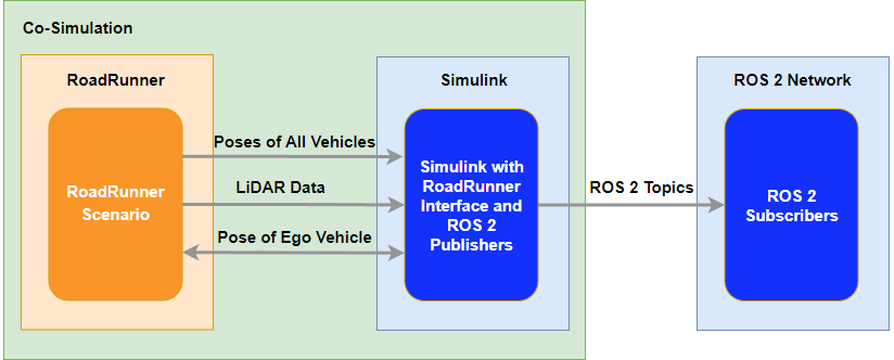
This diagram illustrates the information exchange between RoadRunner Scenario, Simulink and the ROS 2 network:
Prerequisites
This example has these prerequisites:
You have a RoadRunner license and the product is installed. For more information, see Install and Activate RoadRunner (RoadRunner)
You have a RoadRunner Scenario license and the product is installed.
You have created a RoadRunner project folder. For more information, see RoadRunner Project and Scene System (RoadRunner).
Set Up RoadRunner Scenario
This section shows how to configure MATLAB settings to interact with RoadRunner Scenario.
Specify the path to your local RoadRunner installation folder.
rrInstallationPath = "C:\Program Files\RoadRunner R2024a\bin\win64";Specify the path to your RoadRunner project.
rrProjectPath = "C:\RoadRunnerProject";Open RoadRunner using the specified path to your project.
rrApp = roadrunner(rrProjectPath, InstallationFolder=rrInstallationPath);
To open the scenario used in this example, you must copy the files from the example folder into your RoadRunner project folder:
HLFScene.rrscene— RoadRunner scene file that describes the two lane highway.HLFScenario.rrscenario— RoadRunner scenario file that describes actors and their trajectories on the four two highway scene.SLRRCoSim.rrbehavior.rrmeta— Behavior file that associates the sensor processing in Simulink to the ego-vehicle in the RoadRunner Scenario.
copyfile(fullfile(cd,'HLFCurvedRoad.rrscene'),fullfile(rrProjectPath,"Scenes"))
copyfile(fullfile(cd,'HLFScenario.rrscenario'),fullfile(rrProjectPath,"Scenarios"))
copyfile(fullfile(cd,'SLRRCoSim.rrbehavior.rrmeta'),fullfile(rrProjectPath,"Assets","Behaviors"))
Explore the Highway Lane Follower Scenario
Open the highway lane following scenario in RoadRunner.
scenarioName = "HLFScenario";
openScenario(rrApp, strjoin([scenarioName, '.rrscenario'],""));
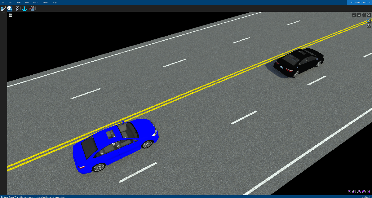
This scenario contains five vehicles. The blue car is the ego-vehicle which contains the sensors and is associated with the custom path following behavior implemented in the Simulink model.
Connect to the RoadRunner Scenario simulation by using the createSimulation function.
rrSim = createSimulation(rrApp);
Connection status: 1
Connected to RoadRunner Scenario server on localhost:60729, with client id {f832f137-c5a6-46c3-b750-b3c88ccbec52}
The Highway Lane Follower application is designed to run at a step size of 0.1 seconds. Set the simulation step size of RoadRunner Scenario to 0.1 seconds, set the max simulation time to 50 seconds, and enable data logging.
simStepSize = 0.1;
maxSimulationTimeSec = 50;
set(rrSim,MaxSimulationTime=maxSimulationTimeSec);
set(rrSim,StepSize=simStepSize);
Inspect Simulink Model
Load the bus definitions used by the RoadRunner scenario elements in the model. If you are using a different scenario or model, you must load the corresponding bus definitions.
load('BusDefinitions.mat');Open the Simulink model SLRRCoSimModel.
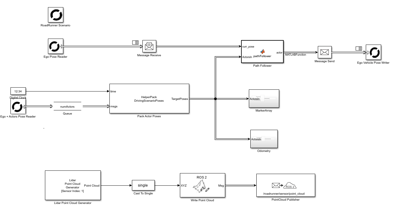
open_system("SLRRCoSimModel.slx");This model reads ground truth and sensor data from the scenario using RoadRunner Scenario Reader block, processes it into ROS 2 messages, and publishes them to the ROS 2 network. You can then visualize the published messages using the ROS Data Analyzer app. It also implements the path follower logic which moves the ego-vehicle along the pre-defined trajectory.
Convert RoadRunner Data to Compatible ROS 2 Messages
You can inspect the MarkerArray and Odometry subsystems to understand the data conversion process for the marker and odometry messages respectively. To convert the lidar sensor data to sensor_msgs/PointCloud2 ROS 2 message, note that the model uses the ROS Write Point Cloud, ROS 2 Write Point Cloud block.
Open the MarkerArray subsystem.
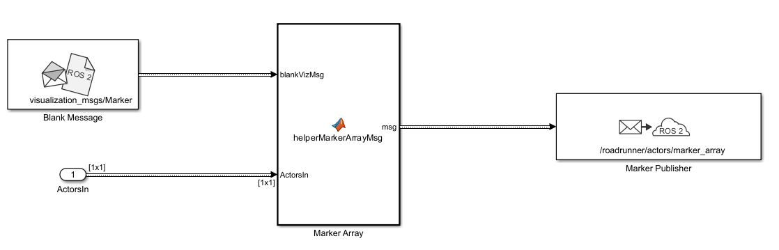
In this subsystem, the helperMarkerArrayMsg function converts the ground-truth position values of each vehicle actor into a ROS 2 visualization_msgs/Marker message. It then concatenates all the marker messages into one visualization_msgs/MarkerArray message and publishes it to the topic /roadrunner/actors/marker_array. Note that the CurrentLength and ReceivedLength fields are necessary for each variable-size array value in the ROS 2 message. The CurrentLength value sets the maximum length of the of the variable-size array, and the ReceivedLength value sets the length of the variable-size array based on the message received on the network. Because this example is constructing the message from known values, set both the CurrentLength and ReceivedLength to the same numerical.
function msg = helperMarkerArrayMsg(blankVizMsg, ActorsIn)
    numActors = length(ActorsIn.Actors);
    egoActorId = 1;

    % Set header for frame
    blankVizMsg.header.frame_id = uint8('map')';
    blankVizMsg.header.frame_id_SL_Info.CurrentLength = uint32(3);
    blankVizMsg.header.frame_id_SL_Info.ReceivedLength = uint32(3);

    % Define color for vehicle markers
    color = repmat(ones(3), numActors, 1);
    for i=1:numActors
        if i == egoActorId
            color(i, :) = [0,0,1];      % Set ego color to blue
        else
            color(i, :) = [0,1,1];      % Set actor color to cyan
        end
    end

    % Prepare Marker Array
    msg = struct('markers', repmat(blankVizMsg, numActors, 1), 'markers_SL_Info', struct('CurrentLength', uint32(numActors), 'ReceivedLength', uint32(numActors)));

    for i=1:numActors
        actor = ActorsIn.Actors(i);
        % Set marker id as ActorID
        blankVizMsg.id = int32(ActorsIn.Actors(i).ActorID);
        blankVizMsg.type = int32(1);
        blankVizMsg.action = int32(0);

        % Set marker color
        blankVizMsg.color.r = single(color(i,1));
        blankVizMsg.color.g = single(color(i,2));
        blankVizMsg.color.b = single(color(i,3));
        blankVizMsg.color.a = single(0.7);

        % Set marker pose
        blankVizMsg.pose.position.x = actor.Position(1);
        blankVizMsg.pose.position.y = actor.Position(2);
        blankVizMsg.pose.position.z = actor.Position(3);

        % Convert Euler angles (degrees) to quaternion
        quats = compact(quaternion([deg2rad(actor.Yaw), deg2rad(actor.Pitch), deg2rad(actor.Roll)],"euler","ZYX","frame"));

        % Assign quaternion to marker orientation
        blankVizMsg.pose.orientation.w = quats(1);
        blankVizMsg.pose.orientation.x = quats(2);
        blankVizMsg.pose.orientation.y = quats(3);
        blankVizMsg.pose.orientation.z = quats(4);

        % Set marker scale
        blankVizMsg.scale.x = 6;
        blankVizMsg.scale.y = 3;
        blankVizMsg.scale.z = 3;

        % blankVizMsg.lifetime.sec = int32(20);
        % blankVizMsg.lifetime.nanosec = uint32(20);

        msg.markers(i) = blankVizMsg;
    end
end
You can open the Odometry subsystems to inspect the conversion process for the odometry message. For more information regarding the odometry message conversion, see the Helper Functions section.
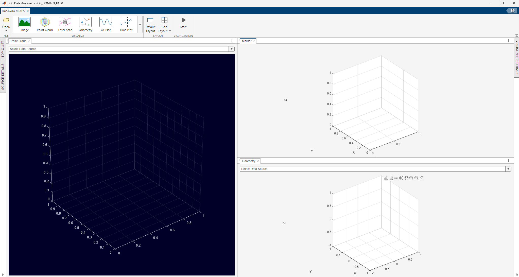
Launch ROS Data Analyzer App
To visualize the ROS 2 messages, launch the ROS Data Analyzer App before running the scenario.
rosDataAnalyzer
Connect to the live ROS 2 network by selecting Open > Live Network Data > Live ROS 2 network data. Specify the ROS Domain ID as 0. To create the Odometry, Marker and Point Cloud visualizers, from the Visualize section of the toolstrip, click Odometry, Point Cloud and Marker.
Simulate Highway Lane Following Scenario
Simulate the scenario and observe how the ego vehicle stays in the current lane and adjusts its speed to avoid collision with the lead vehicle.
set(rrSim,SimulationCommand="Start");Visualize RoadRunner Scenario Data in ROS Data Analyzer App
Once the RoadRunner Scenario starts running, set the data source for the visualizers in the ROS Data Analyzer app to these topics which the Simulink model is publishing to:
Marker Array -
/roadrunner/actors/marker_arrayOdometry -
/roadrunner/ego_vehicle/odomPoint Cloud -
/roadrunner/sensor/point_cloud
You can now visualize the data from the RoadRunner scenario live as published on the ROS 2 network.
Helper Functions
In Odometry subsystem, the helperOdometryMsg function converts the ground-truth position values of ego-vehicle into a ROS 2 nav_messages/Odometry message and publishes it to the topic /roadrunner/ego_vehicle/odom.
function msg = helperOdometryMsg(blankOdomMsg, ActorsIn)
    egoActorID = 1;
    actor = ActorsIn.Actors(egoActorID);
    msg = blankOdomMsg;

    % Create the header structure
    msg.header.frame_id = uint8('map')';
    msg.header.frame_id_SL_Info.CurrentLength = uint32(3);
    msg.header.frame_id_SL_Info.ReceivedLength = uint32(3);

    % Create the position structure
    msg.pose.pose.position.x = actor.Position(1); % Position in x
    msg.pose.pose.position.y = actor.Position(2); % Position in y
    msg.pose.pose.position.z = actor.Position(3); % Position in z

    % Convert Euler angles (degrees) to quaternion
    quats =  compact(quaternion([actor.Yaw, actor.Pitch, actor.Roll],"euler","ZYX","frame"));
    % Assign the orientation structure
    msg.pose.pose.orientation.w = quats(1);
    msg.pose.pose.orientation.x = quats(2);
    msg.pose.pose.orientation.y = quats(3);
    msg.pose.pose.orientation.z = quats(4);

    % Assign the linear velocity structure
    msg.twist.twist.linear.x = actor.Velocity(1); % Linear velocity in x
    msg.twist.twist.linear.y = actor.Velocity(2); % Linear velocity in y
    msg.twist.twist.linear.z = actor.Velocity(3); % Linear velocity in z

    % Assign the angular velocity structure
    msg.twist.twist.angular.x = actor.AngularVelocity(1); % Angular velocity in x
    msg.twist.twist.angular.y = actor.AngularVelocity(2); % Angular velocity in y
    msg.twist.twist.angular.z = actor.AngularVelocity(3); % Angular velocity in z
end
See Also
ROS Data Analyzer | ROS 2 Write Point Cloud
Topics
- Simulate RoadRunner Scenarios with Actors Modeled in Simulink (Automated Driving Toolbox)
- Add Sensors to RoadRunner Scenario Using Simulink (Automated Driving Toolbox)