Detect and Harvest Fruit Using UR10 Manipulator in Gazebo
This example shows how to set up a Universal Robotics UR10 manipulator and simulation environment in Gazebo physics simulator. You configure a simulation in which a robot picks apples from a tree.
This example shows how to simulate a robot that detects and grabs apples from a tree using a Universal Robotics UR10 manipulator by utilizing these toolboxes.
Robotics System Toolbox™— Models, plans and simulates the manipulator in Simulink® and Gazebo.
Navigation Toolbox™— Generates an occupancy map for three-dimensional environments.
Stateflow® — Schedules the high-level tasks in the example and execute them sequentially.
Computer Vision Toolbox™ — Processes 3-D point-cloud data.
Deep Learning Toolbox™ — Detects objects using simulated camera in Gazebo.
Computer Vision Toolbox™ Model for YOLO v4 Object Detection — Provides pretrained YOLO v4 csp-darknet53-coco object detection network.
To use the pretrained YOLO v4 csp-darknet53-coco object detection networks, you must download and install the Computer Vision Toolbox™ Model for YOLO v4 Object Detection from Add-On Explorer. For more information about installing add-ons, see Get and Manage Add-Ons.
The crate model in this example is copyright Arturo Matheus and is licensed under the Free Art License Version 1.3. The original crate model is available at sweethome3d.
Set Up Gazebo Simulation Environment
To set up the simulation environment, follow these steps.
To download the virtual machine (VM) with Gazebo, follow the instructions in Perform Co-Simulation Between Simulink and Gazebo.
In the VM settings, under VM > Settings > Hardware > Display, disable Accelerate 3D graphics. For more information, see Prepare a Virtual Machine to Use Accelerated 3D Graphics.
Start the Ubuntu® VM desktop.
On the Ubuntu desktop, click Gazebo Co-Sim Fruit Picking to start the Gazebo world for this example.
Simulate and Control Robot in Gazebo
This example uses Gazebo Co-Simulation Simulink blocks to connect, read camera images, and read and set joint positions. The Gazebo world contains a Universal Robotics UR10 manipulator robot model with an RGB-Depth (RGB-D) camera sensor. The Gazebo world also contains an apple tree and a crate for collecting apples.
Overview
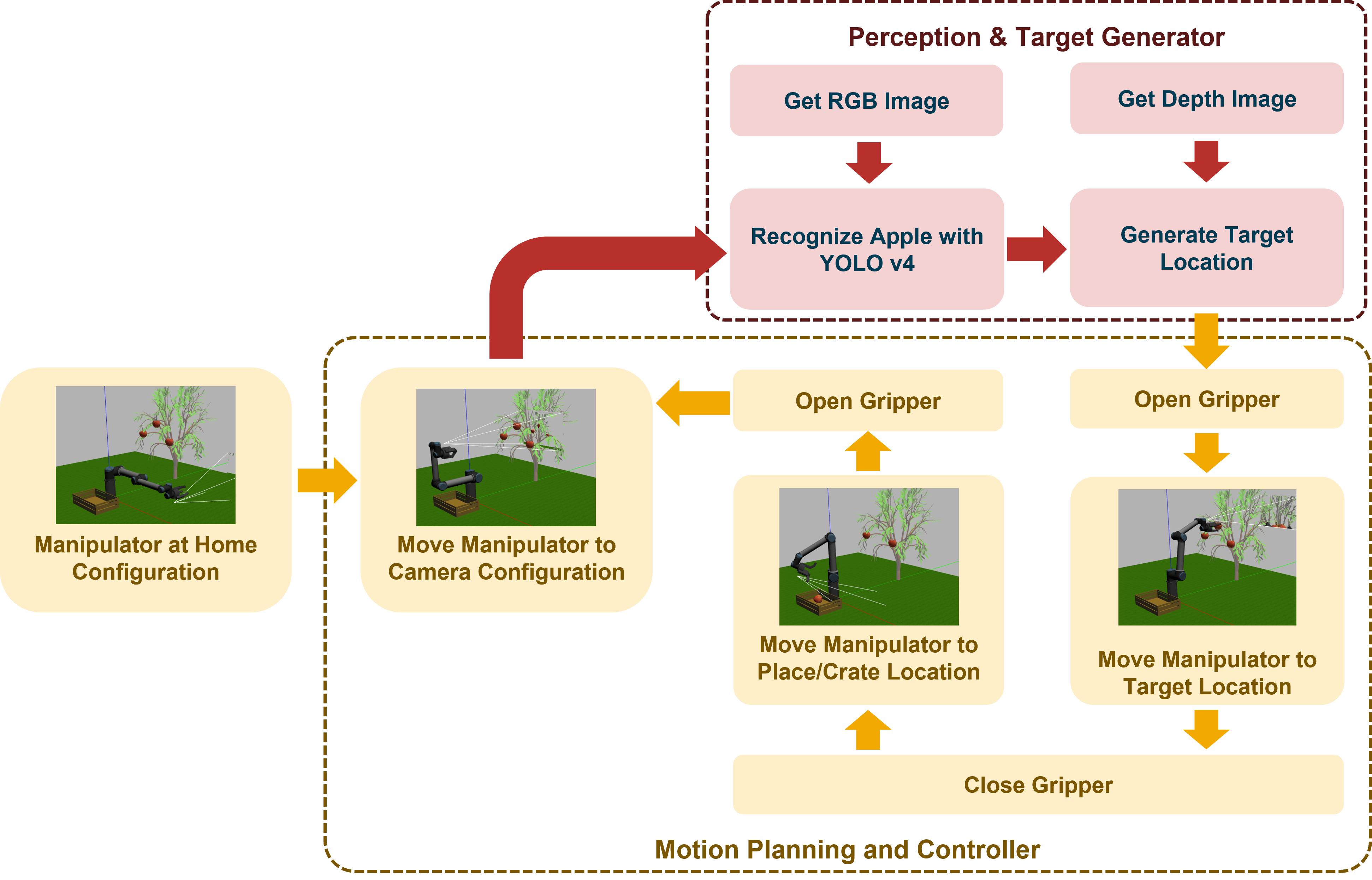
At the start of simulation, the manipulator is in its home configuration. Then, the manipulator moves to the image grab position to collect RGB-D images from Gazebo. When the robot receives the images, it detects and identifies the apples using a YOLO v4 object detection network. The robot then calculates, the target location to the Motion Planning subsystem. The model then uses the manipulatorRRT object to plan motion between the image grab position and the calculated target position. The gripper fingers open while the robot approaches the target apple and close after the robot picks the apple. The model then plans the motion between the target location and the apple drop location. Then, the manipulator moves towards the drop location and opens the gripper to release, placing the apple in the crate. Next, the manipulator moves back to the image grab position. This process continues until the robot removes all the apples are removed from the tree.
Simulink Model
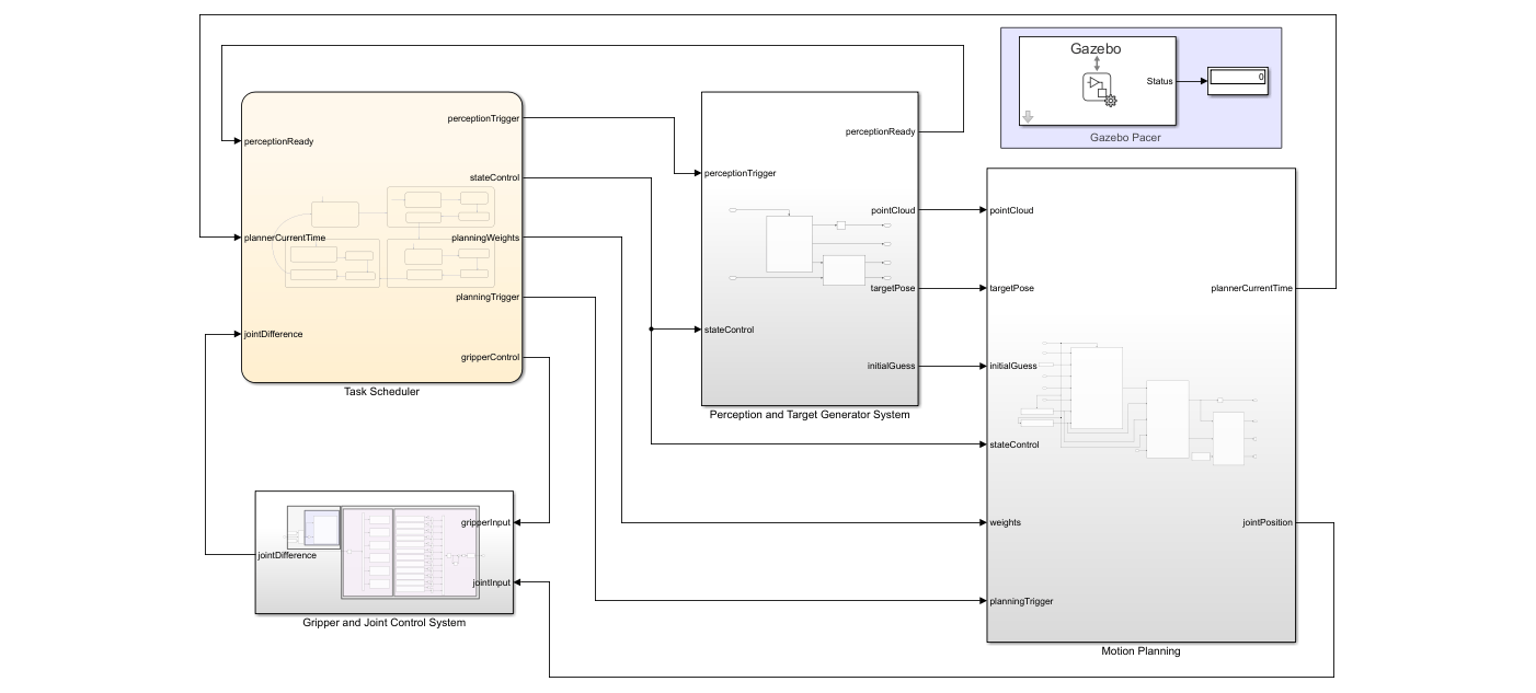
The Simulink model consists of these subsystems.
Task SchedulerPerception and Target Generator SystemMotion PlanningGripper and Joint Control System
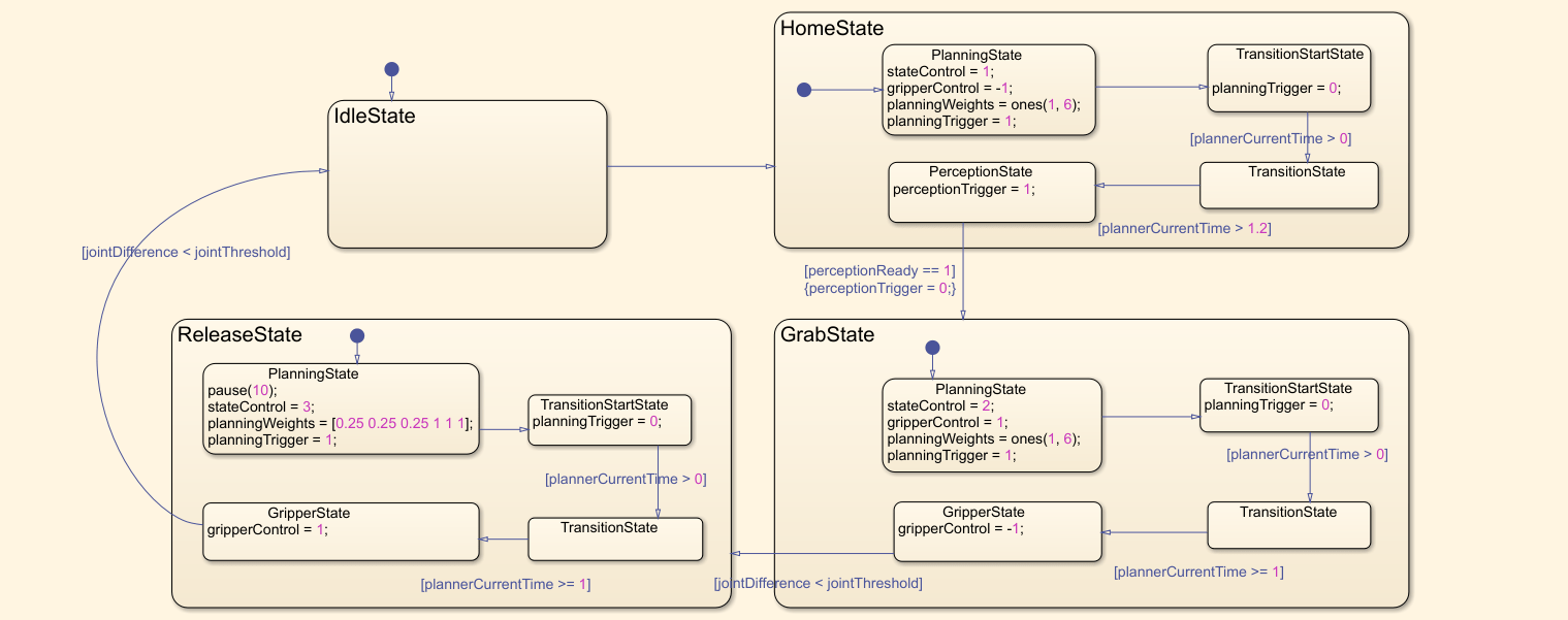
Task Scheduler
A Stateflow chart defines the different states of the robot arm during the pick-and-place workflow. The chart contains these steps.
Initially,
IdleStatetriggers and transits toHomeState.In
HomeState, the current configuration transitions to the image grab configuration through motion planning.When
HomeStateends, it triggersPerceptionStateand captures RGB-D images and transitions toGrabState.For the manipulator to move towards the target,
GrabStatecalculates the target apple locations and performs motion planning.The manipulator opens the gripper while moving towards the target and starts closing the gripper when it reaches the target.
When
GrabStateends, the gripper closes to grab the apple.ReleaseStatethen plans the motion between target position and apple drop location.The manipulator opens the gripper and releases the apple after it reaches the drop location.
The manipulator goes back to
HomeStateto pick an apple from the tree.This process continues until the manipulator grabs all the apples from the tree.
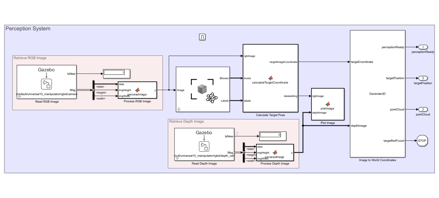
Perception and Target Generator System
The Perception System block and the Target Generator System block query the RGB-D images from Gazebo with the Gazebo Read block and generate the target pose by detecting the target apple through the received RGB-D images.
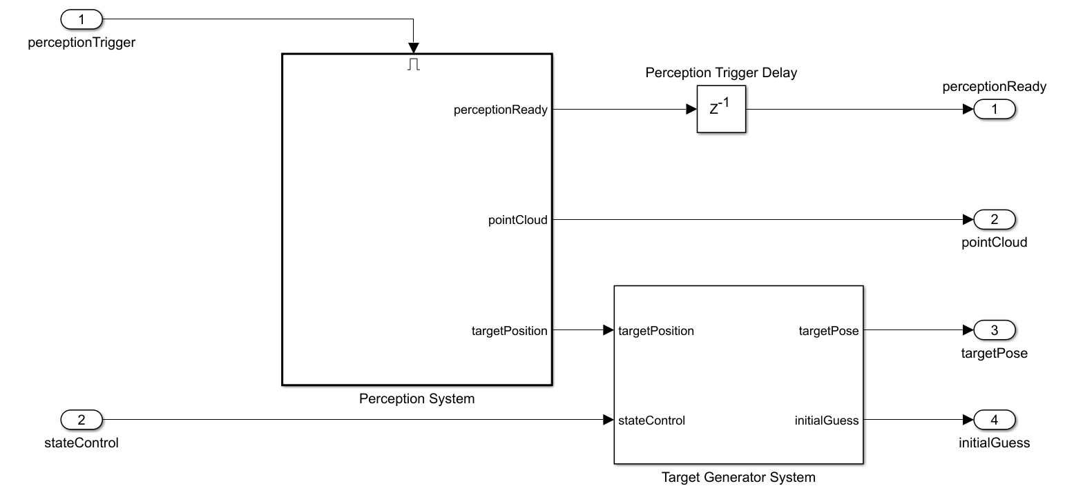
The perception system uses the Deep Learning Object Detector (Computer Vision Toolbox) block to estimate bounding boxes and labels from the input RGB image. The subsystem refines the labels to select only the apple labels. The perception system selects the first apple label as the target apple from the list of all detected apple labels and calculates the 3-D target pose with input depth image. In addition, the subsystem calculates the point cloud, which is required in motion planning, from the input depth image.
Motion Planning
The Perception and Target Generator System generates the target pose and sends it to the Target Configuration Generator block to generate the target joint configuration. The Get Target Pose block calculates the target pose using the manipulator base position, end-effector offset and, current state input. Further, the Inverse Kinematics block calculates the target joint configuration from the calculated target pose, weights, and initial guess.

The Motion Planning block retrieves the current joint configuration from Gazebo and plans the motion using the manipulatorRRT object. Additionally, the subsystem generates a 3-D occupancy map by using the occupancyMap3D (Navigation Toolbox) object for the calculated point cloud. To avoid complex tree structures from the Gazebo world, the subsystem uses this occupancy map as one of the inputs for motion planning. Finally, the subsystem estimates the joint positions based on the calculated waypoints in motion planning.

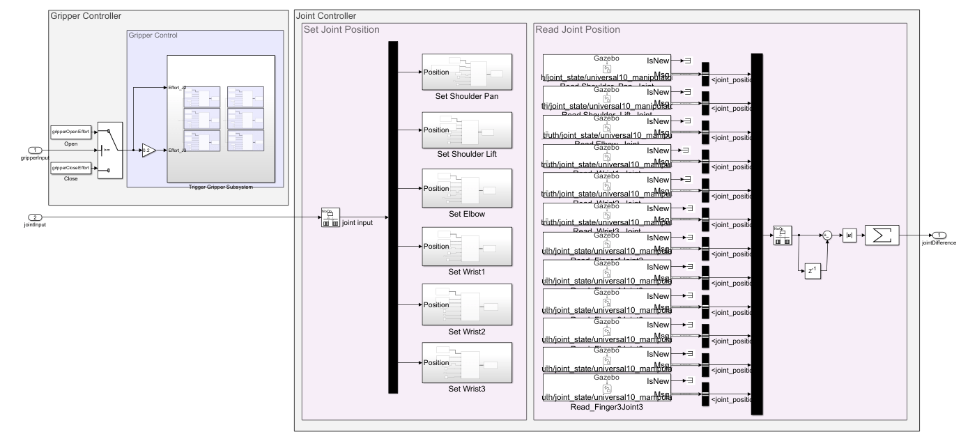
Gripper and Joint Control System
The Gazebo Apply Command block applies the estimated joint positions to the Gazebo model. The Gazebo Read block retrieves the current joint positions from Gazebo. The Gripper Controller module uses the Gazebo Apply Command block to apply torque to each gripper finger joint. Additionally, the state transition in the Task Scheduler calculates the joint difference and uses it to perform state transition.
Assign Parameters for Controlling Robot
Open the Simulink model.
open_system("FruitPickingGazeboManipulator.slx");Define Robot Model and Motion Planning Parameters
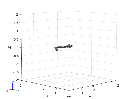
Load and visualize the universalUR10 manipulator using loadrobot.
robot = loadrobot("universalUR10",DataFormat="row",Gravity=[0 0 -9.81]);
show(robot)
ans =
  Axes (Primary) with properties:

             XLim: [-2 2]
             YLim: [-2 2]
           XScale: 'linear'
           YScale: 'linear'
    GridLineStyle: '-'
         Position: [0.1300 0.1100 0.7750 0.8150]
            Units: 'normalized'

  Show all properties
The RGB-D camera and gripper attach to the wrist_3_link of the Universal Robotics UR10 robot model in the Gazebo world. Therefore, specify wrist_3_link as the end-effector.
endEffectorName = "wrist_3_link";Specify the attached gripper offset for the universalUR10 robot model.
endEffectorOffset = [0.0 -0.27 0.0];
Initialize the motion planning parameters.
initializeMotionPlanningParameters
Define Manipulator Pose and Camera Parameters
Load the camera settings to apply in the Gazebo simulator.
initializeCameraParameters
To grab images, define the location to which the universalUR10 robot moves.
imageGrabPositionTform = eye(4);
imageGrabPositionTform(1:3,4) = [0.1639 -0.6120 0.5839];
imageGrabPositionTform(1:3,1:3) = eul2rotm([0 0 0]);
Define the initial guess configuration for the image grab position of the manipulator.
imageGrabPositionInitialGuess = [-pi/2 0 -pi/2 pi/2 -pi/2 pi];
Define the drop location of the picked apple.
releasePositionInitialTform = eye(4);
releasePositionInitialTform(1:3,4) = [-0.1348 -0.5613 0.3530];
releasePositionInitialTform(1:3,1:3) = eul2rotm([5*pi/6 0 -5*pi/6]);
Define the initial guess configuration for the target release position of the manipulator.
releasePositionInitialGuess = [-2*pi/3 -pi/2 2*pi/3 -pi/3 -pi/2 0];
Configure Gazebo Co-Simulation Settings
Define the sample time for the Gazebo Co-Simulation blocks.
Ts = 0.01;
Open the Gazebo Pacer block and click the Configure Gazebo network and simulation settings link. In the Network Address dropdown, select Custom. Enter the IP address of your Linux machine. The default Port value for Gazebo is 14581. Set Response timeout to 10.
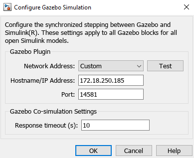
Click the Test button to test the connection to the running Gazebo simulator.
Define Gripper Control Settings
Assign the gripper opening and closing effort values.
gripperOpenEffort = -0.15;
gripperCloseEffort = 0.15;
Simulink Model
To perform simulation and visualize it, click Run.

Visualize the detected apple and depth image in MATLAB®.
