EdgeFeed
R2026bDescription
Use the EdgeFeed object to specify the
FeedDefinitions property in a parent pcbComponent
object.
The EdgeFeed object excites the structure from the edge of the PCB,
typically representing a microstrip or stripline launch.
Creation
Description
f1 = EdgeFeed creates a defaultEdgeFeed
object.
f1 = EdgeFeed( sets
object properties using one or more name-value arguments.
PropertyName=Value)PropertyName is the property name, and Value is
the corresponding value. You can specify several name-value arguments in any order as
PropertyName1=Value1,...,PropertyNameN=ValueN. Properties that you
do not specify retain their default values.
Properties
Examples
This example shows how to instantiate edge feed objects to excite a pcbComponent in stripline configuration.
Convert the default pcbComponent from microstrip format to stripline format by copying its bottom two layers to the top of the layer stack.
p = pcbComponent;
layersTemp = p.Layers;
p.BoardThickness = p.BoardThickness * 2;
p.Layers = [layersTemp(3), layersTemp(2), layersTemp];
The default FeedLocations property has the correct positions for the two feeds. Save this information to a temporary variable. To expose the pcbComponent's FeedDefinitions property set the FeedFormat property to FeedDefinitions.
feedsTemp = p.FeedLocations;
p.FeedFormat = 'FeedDefinitions';
Introduce two EdgeFeed objects to excite the strip against both ground planes simultaneously. The second is a copy of the first with an updated position.
f1 = EdgeFeed('SignalLocations', feedsTemp(1, 1:2), 'SignalLayers', 3, 'GroundLayers', [1; 5], 'SignalWidths', p.Layers{3}.Width);
f2 = copy(f1);
f2.SignalLocations = feedsTemp(2, 1:2);
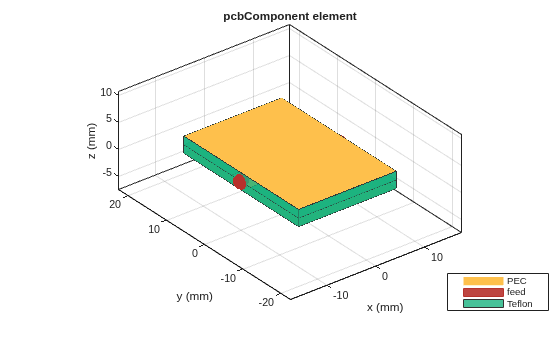
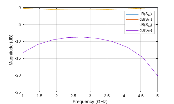
Write the EdgeFeed objects to the pcbComponent's FeedDefinitions property, then show the pcbComponent and calculate its S-parameters.
p.FeedDefinitions = [f1 f2];

figure; show(p);
s = sparameters(p, linspace(1e9, 5e9, 10));
figure; rfplot(s);
Version History
Introduced in R2024b

