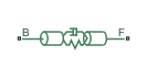
Main Content

Rod

Axially flexible bar or cable

  • Rod block

Libraries:
Simscape / Driveline / Couplings & Drives

Description

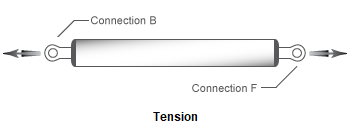
The Rod block represents an axially flexible bar or cable in tension or compression.

Model

To represent the bar or cable, the block uses a lumped parameter model. The model is composed of N+1 lumped masses that are connected in series by N sets of parallel-connected spring and damper circuits. The spring represents elasticity. The damper represents material damping.

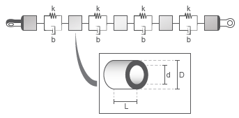
A single flexible element model exhibits an eigenfrequency that is close to the first eigenfrequency of the distributed parameter model. For more accurate analysis, select 2, 4, 8, or more flexible elements.

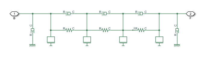
The equivalent physical network contains N spring and damper circuits and N+1 mass blocks. The total mass of the rod is distributed evenly over the mass blocks. The stiffness of the spring in each spring and damper circuit is equal to the N times the stiffness of the rod material.

Equations

The defining equations for the model are:

η=2ζKm2

A=π(D2d2)4

K=EAL

m=ALρ

Where:

  • η is the damping of the rod.

  • ς is the damping ratio of the rod material.

  • K is the stiffness of the rod.

  • A is the cross-sectional area of the rod.

  • D is the outer diameter of the rod.

  • d is the inner diameter of the rod, where

    • d = 0 for a solid rod.

    • d > 0 for an annular, that is, hollow, rod.

  • E is Young's modulus, that is, the modulus of elasticity, of the rod material.

  • L is the length of the rod.

  • m is the mass of the rod.

  • ρ is the density of the rod material.

Assumptions and Limitations

  • The rod does not buckle, in the case of a bar, or go slack, in the case of a cable, in tension.

  • The rod has a constant cross-section along its length.

  • The distributed parameter model is approximated as a finite number of flexible elements, N.

Ports

Conserving

expand all

Translational conserving port associated with rod base or input.

Translational conserving port associated with rod follower or output.

Parameters

expand all

Rod

The table shows how the visibility of some Rod parameters depends on choices that you make for other Rod parameters.

Rod Parameter Dependencies Table

Rod
Parameterization
By stiffness and inertiaBy material and geometry
StiffnessGeometry
MassSolidAnnular
Length
Outer diameter
-Inner diameter
Density
Young's modulus
Damping ratio
Number of flexible elements

Parameterization method.

Each Parameterization option exposes other parameters. For more information, see Rod Parameter Dependencies Table.

Material stiffness.

Setting the Parameterization parameter to By stiffness and inertia exposes this parameter. For more information, see Rod Parameter Dependencies Table.

Rod mass.

Dependencies

Setting the Parameterization parameter to By stiffness and inertia exposes this parameter. For more information, see Rod Parameter Dependencies Table.

Rod cross-sectional geometry.

Dependencies

Setting the Parameterization parameter to By material and geometry exposes this parameter. Each Geometry option exposes other parameters. For more information, see Rod Parameter Dependencies Table.

Rod length.

Dependencies

Setting the Parameterization parameter to By material and geometry exposes this parameter. For more information, see Rod Parameter Dependencies Table.

Rod outer diameter.

Dependencies

Setting the Parameterization parameter to By material and geometry exposes this parameter. For more information, see Rod Parameter Dependencies Table.

Rod inner diameter. If the rod is solid, specify 0.

Dependencies

Setting the Parameterization parameter to By material and geometry and the Geometry parameter to Annular exposes this parameter. For more information, see Rod Parameter Dependencies Table.

Material density.

Dependencies

Setting the Parameterization parameter to By material and geometry exposes this parameter. For more information, see Rod Parameter Dependencies Table.

Young's modulus for the rod material.

Dependencies

Setting the Parameterization parameter to By material and geometry exposes this parameter. For more information, see Rod Parameter Dependencies Table.

Material damping ratio.

Number of flexible elements, N, for the approximation.

A larger number of flexible elements, N, increases the accuracy of the model but reduces simulation performance, that is, simulation speed. The single-element model (N=1) exhibits an eigenfrequency that is close to the first eigenfrequency of the continuous, distributed parameter model.

If accuracy is more important than performance, select 2, 4, 8, or more flexible elements. For example, the four lowest eigenfrequencies are represented with an accuracy of 0.1, 1.9, 1.6, and 5.3 percent, respectively, by a 16-element model.

Viscous Losses

Viscous friction coefficients at base port, B, and the follower port, F.

Initial Conditions

Deflection of the rod at the start of simulation.

A positive initial deflection results in a positive translation of the base, B, end of the rod relative to the follower, F, end of the rod.

Longitudinal velocity of the base, B, end of the rod relative to the follower, F, end of the rod at the start of simulation.

Extended Capabilities

C/C++ Code Generation
Generate C and C++ code using Simulink® Coder™.

Version History

Introduced in R2018b