Radar Waveform Generator
Description
The Radar Waveform Generator app lets you generate radar waveforms found in the Phased Array System Toolbox™. The app generates these waveforms:
Waveforms
FMCW
Linear FM
Rectangular
Phase Coded
Nonlinear FM
All other waveforms available in Wireless Waveform Generator (Communications Toolbox) found in the Communications Toolbox™.
Using the app, you can:
App capabilities
Export these waveforms to your workspace or to a
.mator.bbfile.Export waveform generation code and parameters to a runnable MATLAB® script or a Simulink® block.
Use the exported script to generate your waveform, without the app, from the command line.
Use the exported block as a waveform source in a Simulink model. For more information, see the Create Waveforms Using Wireless Waveform Generator App (Communications Toolbox) block.
Visualize the waveform using
Visualization
Time Scope
Spectrum Analyzer
Spectrogram
Ambiguity Function
Autocorrelation Function
Distort the waveforms by adding radio frequency (RF) impairments, such as additive white Gaussian noise (AWGN), phase offset, frequency offset, DC offset, in-phase and quadrature (IQ) imbalance, and memoryless cubic nonlinearity.
Exporting waveforms
Use the app to create waveforms in your workspace or save them to a
.mat,.bb, or.txtfile.Use the exported script to generate your waveform without the app from the command line.
Use the exported block as a waveform source in a Simulink model. The exported block name is derived from the name of the waveform.
Open the Radar Waveform Generator App
MATLAB toolstrip: On the Apps tab, under Radar and Tracking select the Radar Waveform Generator app.

Alternatively, at the MATLAB command line, enter
radarWaveformGenerator.
Examples
Open the Radar Waveform Generator from the Apps gallery .
From the Generator tab, select the FMCW icon.
Set the Sweep time (s) to 0.01 sec.
Set the Sweep direction to
Down.Select a
SymmetricSweep interval.Set the Number of sweeps to three.
From the Visualize tab, select Time scope and Spectrum analyzer displays and then generate the plots.
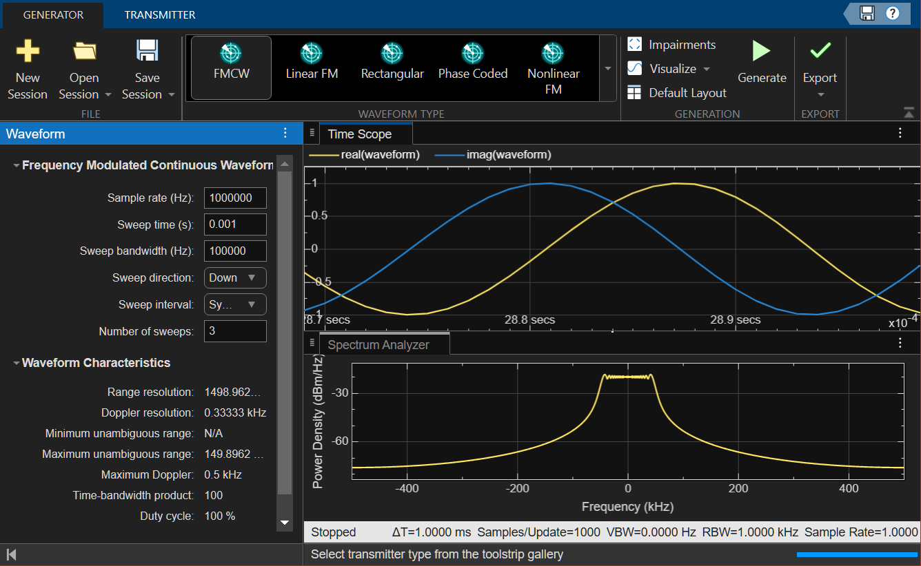
The time scope displays the real and imaginary parts of the waveform. The spectrum analyzer displays the power density.
Open the Radar Waveform Generator from the Apps gallery.
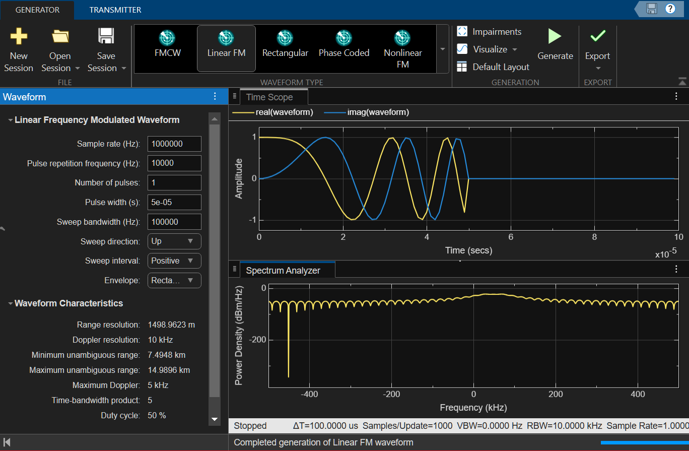
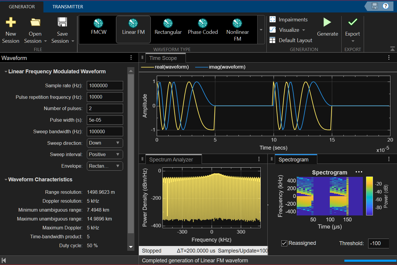
From the Generator tab, select the Linear FM icon.
Set the Sample rate (Hz) to 1000000.
Set the Pulse repetition frequency (Hz) to 10000.
Set the Number of pulses to 2.
Set the Pulse width (s) to 5e05.
Set the Sweep bandwidth (Hz) to 10000.
Set the Sweep direction to
Down.Select a
PositiveSweep interval.Select the Envelope as
Rectangular.From the Visualize tab, select Time scope, Spectrum analyzer, and Spectrogram to display the plots.
Open the Radar Waveform Generator from the Apps gallery.
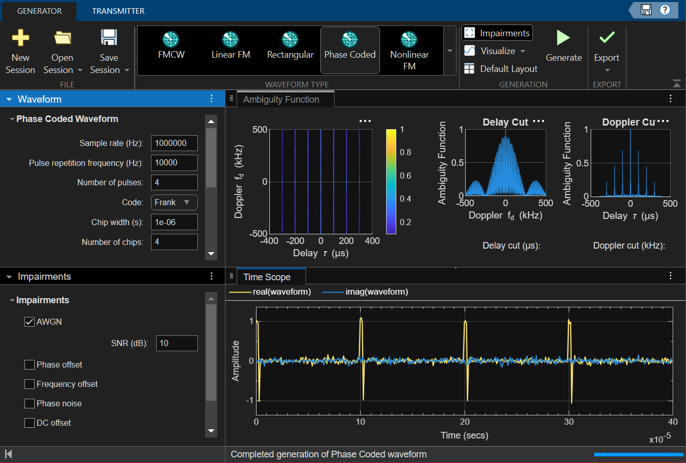
From the Generator tab, select the Phase Coded Waveform icon.
Set the Sample rate (Hz) to 1000000.
Set the Pulse repetition frequency (Hz) to 5000.
Set the Number of pulses to 4.
Set the Code to
Frank.Set the Chip width (s) to 1e-06.
Set the Number of chips to 4.
Open the Impairments tab and select the select the AWGN impairment. Set the SNR (db) value to 10 to show a higher noise level.
From the Visualize tab, select Time Scope,and Ambiguity Function to display the plots.
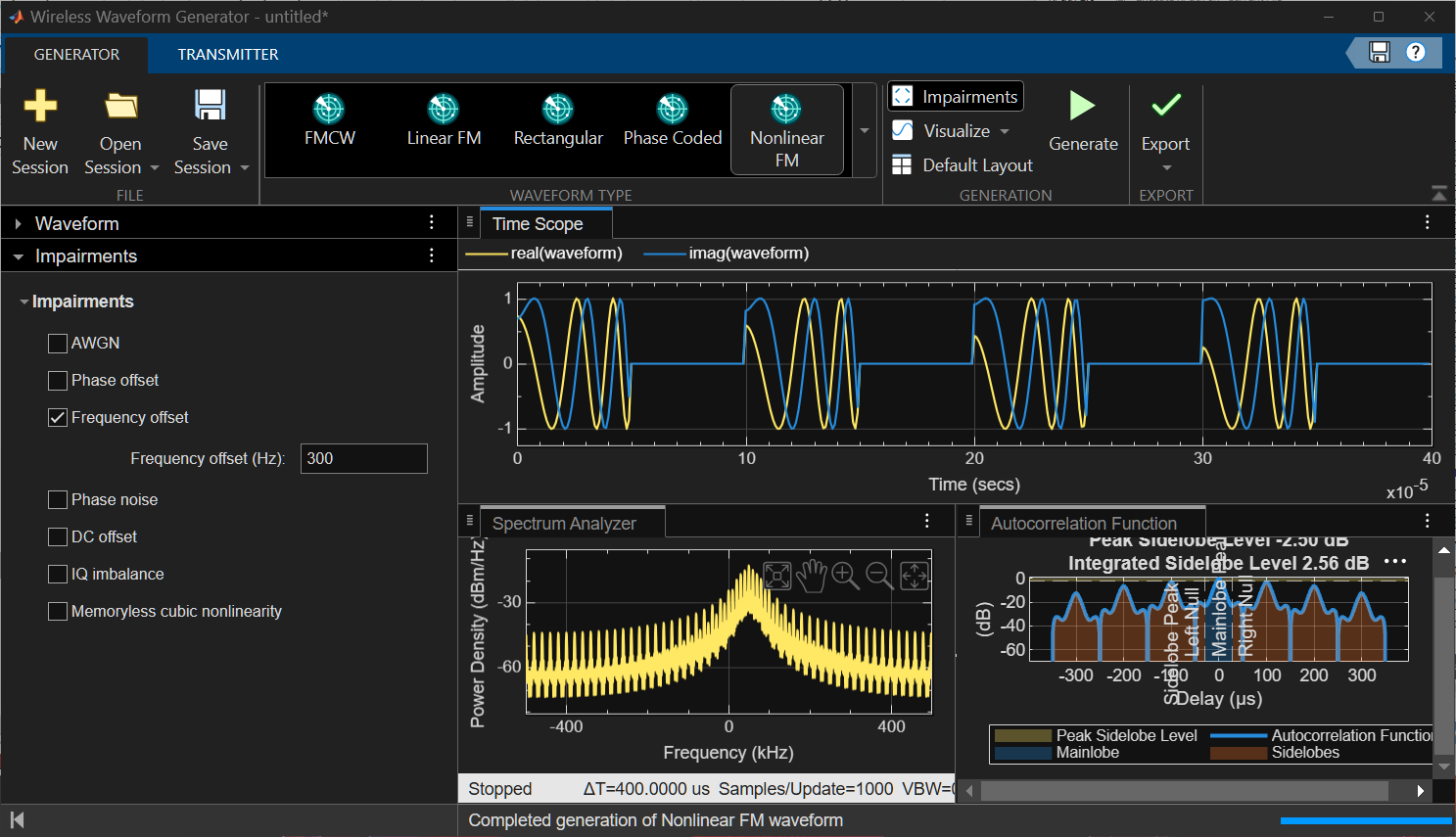
Open the Radar Waveform Generator from the Apps gallery.
From the Generator tab, select the Nonlinear FM icon.
Set the Sample rate (Hz) to 1000000.
Set the Pulse repetition frequency (Hz) to 10000.
Set Frequency modulation to
Hybrid Linear-Tangent.Set Linear-tangent balance to 0.5.
Set Tangent curve portion to 1.4.
Set the Number of pulses to 4.
Set the Pulse width (s) to
5e-05.Set the Sweep bandwidth (Hz) to 100000.
Set the Sweep direction to
Up.Select a
PositiveSweep interval.Select the Envelope as
Rectangular.Open the Impairments tab and select the select the Frequency offset impairment. Set the
Frequency
              offset (Hz)
value to 300.From the Visualize tab, select Time Scope,Spectrum Analyzer, and Autocorrelation Function to display the plots.
Parameters
Algorithms
The app supports different waveform impairments. A more detailed explanation of these impairments can be found in the Communications Toolbox when available.
Impairments
Impairment Units Default value AWGN SNR (dB) 20 Phase offset phase offset (dB) pi/8 Frequency offset Frequency offset (Hz) 10 Phase Noise Levels (dBc/Hz) [-60 -80] Frequency offsets (Hz) [200000 400000] DC offset DC offset (V) 0.1+0.2i IQ imbalance Amplitude imbalance (dB) 8 Phase imbalance (rad) pi/5 Memoryless cubic nonlinearity Linear gain (dB) 0 IIP3 (dBm) 30 AM/PM conversion (deg/dB) 10
References
[1] Collins, T., and P. Atkins. "Nonlinear frequency modulation chirps for active sonar." IEE Proceedings-Radar, Sonar and Navigation 146.6 (1999): 312-316.
[2] Levanon, N. and E. Mozeson. Radar Signals. Hoboken, NJ: John Wiley & Sons, 2004.
Version History
Introduced in R2026a
See Also
Apps
- Wireless Waveform Generator (Communications Toolbox)
Blocks
- Create Waveforms Using Wireless Waveform Generator App (Communications Toolbox)