Main Content

polsignature

Copolarization and cross-polarization signatures

Description

resp = polsignature(rcsmat) returns the normalized radar cross-section copolarization (co-pol) signature, resp (in square meters), determined from the scattering cross section matrix, rcsmat of an object. The signature is a function of the transmitting antenna polarization, specified by the ellipticity angle and the tilt angle of the polarization ellipse. In this syntax case, the ellipticity angle takes the values [-45:45] and the tilt angle takes the values [-90:90]. The output resp is a 181-by-91 matrix whose elements correspond to the signature at each ellipticity angle-tilt angle pair.

example

resp = polsignature(rcsmat,type), in addition, specifies the polarization signature type as one of 'c'|'x', where 'c' creates the copolarization signature and 'x' creates the cross-polarization (cross-pol) signature. The default value of this parameter is 'c'. The output resp is a 181-by-91 matrix whose elements correspond to the signature at each ellipticity angle-tilt angle pair. This syntax can use the input arguments in the previous syntax.

example

resp = polsignature(rcsmat,type,epsilon), in addition, specifies the transmit antenna polarization's ellipticity angle (in degrees) as a length-M vector. The angle epsilon must lie between –45° and 45°. The argument resp is a 181-by-M matrix whose elements correspond to the signature at each ellipticity angle-tilt angle pair. This syntax can use any of the input arguments in the previous syntaxes.

example

resp = polsignature(rcsmat,type,epsilon,tau), in addition, specifies the tilt angle of the polarization ellipse of the transmitted wave (in degrees) as a length-N vector. The angle tau must be between –90° and 90°. The signature, resp, is represented as a function of the transmitting antenna polarization. The transmitting antenna polarization is characterized by the ellipticity angle, epsilon, and the tilt angle, tau. The argument resp is a N-by-M matrix whose elements correspond to the signature at each ellipticity angle-tilt angle pair. This syntax can use any of the input arguments in the previous syntaxes.

example

polsignature(___) plots a three dimensional surface using any of the syntax forms specified above.

example

Examples

collapse all

Calculate and plot the copolarization response to the scattering cross-section matrix, rscmat, of a dihedral object. Specify the ellipticity angle values as [-45:45] and the tilt angle values as [-90:90]. Display the response matrix as an image.

Calculate the copolarization response.

rscmat = [-1,0;0,1];
resp = polsignature(rscmat);

Plot the copolarization response.

el = [-45:45];
tilt = [-90:90];
imagesc(el,tilt,resp);
ylabel('Tilt (degrees)');
xlabel('Ellipticity Angle (degrees)')
axis image
ax = gca;
ax.XTick = [-45:15:45];
ax.YTick = [-90:15:90];
title('Co-polarization signature of dihedral');
colorbar;

Figure contains an axes object. The axes object with title Co-polarization signature of dihedral, xlabel Ellipticity Angle (degrees), ylabel Tilt (degrees) contains an object of type image.

Calculate and plot the cross-polarization response to the scattering cross-section matrix, rscmat, of a dihedral object. Specify the ellipticity angle values as [-45:45] and the tilt angle values as [-90:90]. Display the response matrix as an image.

Calculate the cross-polarization response. To do this, set the type argument to 'x'.

rscmat = [-1,0;0,1];
resp = polsignature(rscmat,'x');

Plot the cross-polarization response.

el = [-45:45];
tilt = [-90:90];
imagesc(el,tilt,resp);
ylabel('Tilt (degrees)');
xlabel('Ellipticity Angle (degrees)');
axis image
ax = gca;
ax.XTick = [-45:15:45];
ax.YTick = [-90:15:90];
title('Cross-polarization signature of dihedral');
colorbar;

Figure contains an axes object. The axes object with title Cross-polarization signature of dihedral, xlabel Ellipticity Angle (degrees), ylabel Tilt (degrees) contains an object of type image.

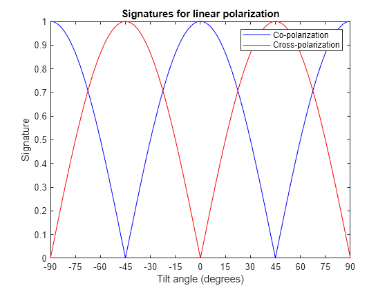
Set the ellipticity angle to zero, and vary the tilt angle from -90 to +90 degrees to generate all possible linear polarization directions. Then, plot both the copolarization and cross-polarization signatures.

rscmat = [-1,0;0,1];
el = [0];
respc = polsignature(rscmat,'c',el);
respx = polsignature(rscmat,'x',el);
tilt = [-90:90];
plot(tilt,respc,'b',tilt,respx,'r')
ax = gca;
ax.XLim = [-90,90];
ax.XTick = [-90:15:90];
legend('Co-polarization','Cross-polarization')
title('Signatures for linear polarization')
xlabel('Tilt angle (degrees)')
ylabel('Signature')

Figure contains an axes object. The axes object with title Signatures for linear polarization, xlabel Tilt angle (degrees), ylabel Signature contains 2 objects of type line. These objects represent Co-polarization, Cross-polarization.

This example shows how to obtain numerical values for the polarization signatures of a dihedral target for left and right circularly polarized incident waves.

Specify the radar cross-section matrix of a dihedral

rscmat = [-1,0;0,1];

Specify a left circularly-polarized wave and obtain its tilt angle and ellipticity.

fv = 1/sqrt(2)*[1;1i];
[tilt_lcp,el_lcp] = polellip(fv);
disp([tilt_lcp,el_lcp])
    45    45

Specify a right circularly-polarized wave by complex conjugation of a left circularly-polarized wave. Obtain the polarization ellipse tilt angle and ellipticity.

[tilt_rcp,el_rcp] = polellip(conj(fv));
disp([tilt_rcp,el_rcp])
    45   -45

Both tilt angles are 45 degrees. Compute the copolarization and cross-polarization signatures for the two waves.

el = [el_lcp, el_rcp];
tilt = tilt_rcp;
respc = polsignature(rscmat,'c',el,tilt);
respx = polsignature(rscmat,'x',el,tilt);
disp(respc)
     1     1
disp(respx)
     1     1

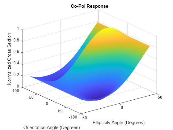
Use a general RCSM matrix to create a 3-D surface plot.

rscmat = [1i*2,0.5; 0.5, -1i];
el = [-45:45];
tilt = [-90:90];

With no output arguments, polsignature automatically creates a surface plot.

polsignature(rscmat,'c',el,tilt);

Figure contains an axes object. The axes object with title Co-Pol Response, xlabel Ellipticity Angle (Degrees), ylabel Orientation Angle (Degrees) contains an object of type surface.

Input Arguments

collapse all

Radar cross-section scattering matrix (RCSM) of an object specified as a 2-by-2, complex-valued matrix. The radar cross-section scattering matrix describes the polarization of a scattered wave as a function of the polarization of an incident wave upon a target. The response to an incident wave can be construct from the individual responses to the incident field’s horizontal and vertical polarization components. These components are taken with respect to the transmit antenna or array local coordinate system. The scattered wave can be decomposed into horizontal and vertical polarization components with respect to the receive antenna or array local coordinate system. The matrix RCSM contains four components [rcs_hh rcs_hv;rcs_vh rcs_vv] where each component is the radar cross section defined by the polarization of the transmit and receive antennas.

  • rcs_hh – Horizontal response due to horizontal transmit polarization component

  • rcs_hv – Horizontal response due to vertical transmit polarization component

  • rcs_vh – Vertical response due to horizontal transmit polarization component

  • rcs_vv – Vertical response due to vertical transmit polarization component

In the monostatic radar case, when the wave is backscattered, the RCSM matrix is symmetric.

Example: [-1,1i;1i,1]

Data Types: double
Complex Number Support: Yes

Polarization signature type of the scattered wave specified by a single character: 'c' denoting the copolarized signature or 'x' denoting the cross-polarized signature.

Example: 'x'

Data Types: char

Ellipticity angle of the polarization ellipse of the transmitted wave specified as a length-M vector. Units are degrees. The ellipticity angle describes the shape of the ellipse. By definition, the tangent of the ellipticity angle is the signed ratio of the semiminor axis to semimajor axis of the polarization ellipse. Since the absolute value of this ratio cannot exceed unity, the ellipticity angle lies between ±45°.

Example: [-45:0.5:45]

Data Types: double

Tilt angle of the polarization ellipse of the transmitted wave specified as a length-N vector. Units are degrees. The tilt angle is defined as the angle between the semimajor axis of the ellipse and the x-axis. Because the ellipse is symmetrical, an ellipse with a tilt angle of 100° is the same ellipse as one with a tilt angle of –80°. Therefore, the tilt angle need only be specified between ±90°.

Example: [-30:2:30]

Data Types: double

Output Arguments

collapse all

Normalized magnitude response returned as a scalar or N-by-M, real-valued matrix having values between 0 and 1. resp returns a value for each ellipticity-tilt angle pair.

More About

collapse all

Scattering Cross-Section Matrix

Scattering cross-section matrix determines response of an object to incident polarized electromagnetic field.

When a polarized plane wave is incident on an object, the amplitude and polarization of the scattered wave may change with respect to the incident wave polarization. The polarization may depend upon the direction from which the scattered wave is observed. The exact way that the polarization changes depends upon the properties of the scattering object. The quantity describing the response of an object to the incident field is called the scattering cross-section matrix, S. The scattering matrix can be measured as follows: when a unit amplitude horizontally polarized wave is scattered, both a horizontal and vertical scattered component are produced. Call these two components SHH and SVH. These are complex numbers containing the amplitude and phase changes from the incident wave. Similarly, when a unit amplitude vertically polarized wave is scattered, the horizontal and vertical scattered component produced are SHV and SVV. Because any incident field can be decomposed into horizontal and vertical components, stack these quantities into a matrix and write the scattered field in terms of the incident field

[EH(sc)EV(sc)]=[SHHSVHSHVSVV][EH(inc)EV(inc)]=S[EH(inc)EV(inc)]

The scattering cross section matrix depends upon the angles that the incident and scattered fields make with the object. When the incident field is backscattered to the transmitting antenna, the scattering matrix is symmetric.

Polarization Signature

Polarization signature for visualizing scattering cross-section matrix.

To understand how the scattered wave depends upon the polarization of the incident wave, an examination of all possible scattered field polarizations for each incident polarization is required. Because this amount of data is difficult to visualize, you can look at two particular scattered polarizations:

  • Choose one polarization that has the same polarization as the incident field (copolarization)

  • Choose a second one that is orthogonal to the polarization of the incident field (cross-polarization)

Both the incident and orthogonal polarization states can be specified in terms of the tilt angle-ellipticity angle pair (τ,ε). From the incident field tilt and ellipticity angles, the unit incident polarization vector can be expressed as

[EH(inc)EV(inc)]=[cosτsinτsinτcosτ][cosεjsinε]

while the orthogonal polarization vector is

[EH(inc)EV(inc)]=[sinτcosτcosτsinτ][cosεjsinε]

To form the copolarization signature, use the RCSM matrix, S, to compute:

P(co)=[EH(inc)EV(inc)]*S[EH(inc)EV(inc)]

where []* denotes complex conjugation. For the cross-polarization signature, compute

P(cross)=[EH(inc)EV(inc)]*S[EH(inc)EV(inc)]

The output of this function is the absolute value of each signature normalized by its maximum value.

References

[1] Mott, H. Antennas for Radar and Communications.John Wiley & Sons, 1992.

[2] Fawwaz, U. and C. Elachi. Radar Polarimetry for Geoscience Applications. Artech House, 1990.

[3] Lee, J. and E. Pottier. Polarimetric Radar Imaging: From Basics to Applications. CRC Press, 2009.

Extended Capabilities

Version History

Introduced in R2013a

See Also

| |