minvarweights
Syntax
Description
wts = minvarweights(pos,ang)wts for synthesizing the pattern
of a sensor array in the direction specified by ang. Array element
positions are specified in pos. The function optimizes the beamforming
weights using a second-order cone programming solver. This function requires Optimization Toolbox™.
Examples
Compute optimized beamforming weights of a 31-element half-wavelength spacing ULA in the direction of degree in azimuth. Design the array to keep sidelobe levels less than -23 dB.
Create the optimized weights.
N = 31;
pos = (0:N-1)*0.5;
sll = -23;
wts = minvarweights(pos,-30,MaskSidelobeLevel=sll);
Apply the optimized weights and display the array pattern from to azimuth.
az = -90:.25:90;
pat_opt = arrayfactor(pos,az,wts);
plot(az,mag2db(abs(pat_opt)))
xlabel('Azimuth Angle (deg)')
ylabel('Beam Pattern (dB)')
xlim([-90,90])

Design an array to have a tapered beampattern, The array is a 51-element half-wavelength spacing ULA steered in the direction of in azimuth. The pattern synthesis goal is to achieve sidelobe levels smaller than a tapered mask decreasing linearly from -18 dB to -55 dB at . Place nulls at , , and azimuth angle.
N = 51;
pos = (0:N-1)*0.5;
ANGmainBeam = 25;
angn = [-35 -45 40];
angm = [-90:.2:22 27:0.2:90];
sllm = [linspace(-55,-18,length(-90:.2:22)) ...
    linspace(-18,-55,length(27:.2:90))];
wts = minvarweights(pos,ANGmainBeam,'MaskAngle',angm, ...
    'MaskSidelobeLevel',sllm,'NullAngle',angn);
Apply optimized weights and display the array pattern from to in azimuth.
az = -90:.25:90;
pat_opt = arrayfactor(pos,az,wts);
plot(az,mag2db(abs(pat_opt)))
axis([-90 90 -125 5])
xlabel('Azimuth Angle (deg)')
ylabel('Beam Pattern (dB)')
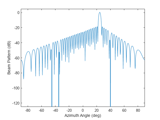
Verify that nulls are placed at , , and azimuth angle.
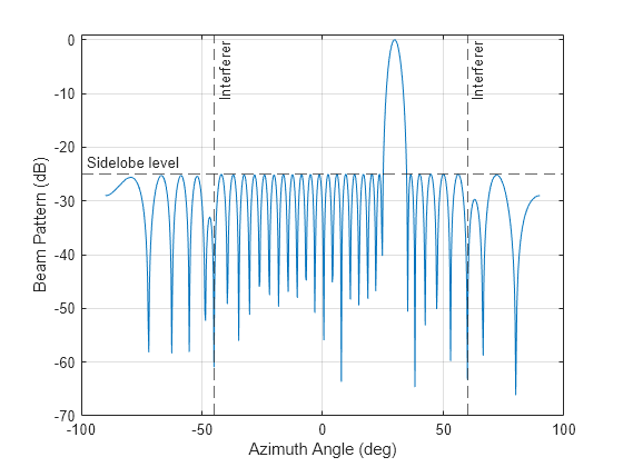
Calculate the optimized beamforming weights for a 32-element, half-wavelength spacing ULA. The look direction (angs) is 30 degrees in azimuth. There are two interfering signals coming from azimuths 60 and -45 degrees, respectively (angi). The signal-free spatial covariance matrix contains contributions from the noise and the interferers only. The noise is white across all elements and the SNR (snr) is 10 dB. The pattern synthesis goal is to keep the sidelobe level (sll) below -25 dB and to point nulls at the interferers.
N = 32;
d = 0.5;
pos = (0:N-1)*d;
angs = 30;
angi = [-45 60];
Find the sensor covariance matrix and then the array weights.
snr= 10;
cov = sensorcov(pos,angi,db2pow(-snr));
sll = -25;
wts = minvarweights(pos,angs,cov,'MaskSidelobeLevel',sll);
Find the array pattern.
az = -90:.25:90;
pat_opt = arrayfactor(pos,az,wts);
Plot the array pattern as a function of azimuth (az).
plot(az,mag2db(abs(pat_opt)))
xline(angi(1),'--','Interferer')
xline(angi(2),'--','Interferer')
yline(sll,'--','Sidelobe level', ...
    'LabelHorizontalAlignment','left')
xlabel('Azimuth Angle (deg)')
ylabel('Beam Pattern (dB)')
ylim([-70 1])
grid on
Input Arguments
Output Arguments
References
[1] Lebret, H., and S. Boyd. “Antenna Array Pattern Synthesis via Convex Optimization.” IEEE Transactions on Signal Processing, vol. 45, no. 3, Mar. 1997, pp. 526–32. DOI.org (Crossref), https://doi.org/10.1109/78.558465.
[2] Golbon-Haghighi, Mohammad-Hossein, et al. “Design of a Cylindrical Crossed Dipole Phased Array Antenna for Weather Surveillance Radars.” IEEE Open Journal of Antennas and Propagation, vol. 2, 2021, pp. 402–11. DOI.org (Crossref), https://doi.org/10.1109/OJAP.2021.3059471.
Version History
Introduced in R2022b
See Also
steervec | cbfweights | lcmvweights | sensorcov | phased.MVDRBeamformer | phased.LCMVBeamformer