readDigitalPin
Read logical value from GPIO input pin
Add-On Required: This feature requires the MATLAB Support Package for Raspberry Pi Hardware add-on.
Description
Examples
Configure Pin as Input and Read Its Value
Configure a GPIO pin as
digital input and read its logical value.
Create a connection from MATLAB® to the Raspberry Pi® board.
mypi = raspi
mypi =

  Raspi with Properties:

           DeviceAddress: 'raspberrypi-hysdu8X38o'
                    Port: 18725
               BoardName: 'Raspberry Pi Model B Rev 2'
           AvailableLEDs: {'led0'}
    AvailableDigitalPins: [4 7 8 9 10 11 14 15 17 18 22 23 24 25 27 30 31]
    AvailableSPIChannels: {}
       AvailableI2CBuses: {'i2c-0'  'i2c-1'}
             I2CBusSpeed: 100000
The AvailableDigitalPins property shows the
list of available digital GPIO pins.
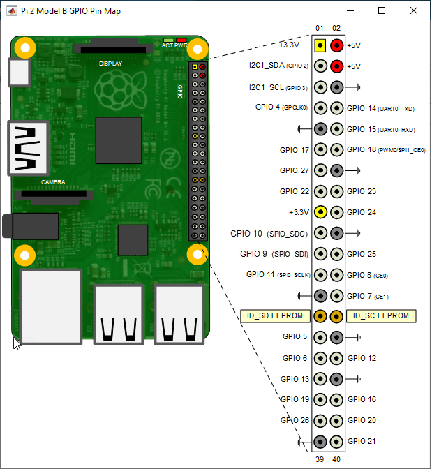
Show the location of all the GPIO pins
on your device.
showPins(mypi)

Display the AvailableDigitalPins.
mypi.AvailableDigitalPins
ans =

  Columns 1 through 13

     4  7  8  9  10  11  14  15  17  18  22  23  24

  Columns 14 through 17

    25  27  30  31
Connect your digital device to the first GPIO pin
available, for example GPIO 4.
Configure pin GPIO 4 as a digital input.
configurePin(mypi,4,'DigitalInput')Read the value from pin GPIO 4.
readDigitalPin(mypi,4)
ans =

  1
The logical value of 1 indicates a positive
voltage signal on the pin GPIO 4.
Press a Button to Blink an LED
This example shows how to use a button to blink an LED attached to a GPIO pin.
When you press a button, this example rapidly blinks an LED.
The button connects from positive voltage to pin 23. Pressing the
button closes the circuit, raising the voltage. When readDigitalPin
detects the positive voltage, if buttonPressed becomes
true. The program toggles the voltages to pin 24 on and off 10 times.
Pin 14 connects to an LED, which connects via a resistor to ground.
for ii = 1:100
    buttonPressed = readDigitalPin(mypi,23)
    if buttonPressed
        for jj = 1:10
            writeDigitalPin(mypi,24,1)
            pause(0.05)
            writeDigitalPin(mypi,24,0)
            pause(0.05)
        end
    end
    pause(0.1)
end