UMTS Parameterization Overview
Many parameters must be defined to generate UMTS waveforms. To organize parameters for initialization, review, and use, the LTE Toolbox™ product groups relevant UMTS parameters into structures.
To generate downlink or uplink UMTS waveforms, you must define the waveform properties and the channels you want to include in the waveforms. Separate downlink and uplink configuration structures consolidate the parameters required to initialize and generate a waveform for the target link direction.
Downlink Reference Channel and Waveform Generation Parameter Structures
Defining a downlink waveform requires initialization of a handful of top-level
parameters and substructures associated with permissible channels. The top-level
parameters include TotFrames,
PrimaryScramblingCode, FilterType,
OversamplingRatio, and NormalizedPower. The
channel substructures can include combinations of these channels:
DPCH, PCCPCH, SCCPCH,
PCPICH, SCPICH, PSCH,
SSCH, PICH, HSDPA, and
OCNS. You only include and initialize the individual channel
substructures needed to generate desired waveform.
The umtsDownlinkReferenceChannels function
initializes the configuration structure based on an input character vector argument
aligning with one of the reference channels defined in these 3GPP standards:
You can generate waveforms using umtsDownlinkWaveformGenerator with an input configuration structure that you:
Initialize by calling
umtsDownlinkReferenceChannels, specifying one of the predefined reference channels as an inputInitialize to one of the predefined reference channels as above, and adjust settings manually
Manually initialize, complying with the structure defined as input to
umtsDownlinkWaveformGenerator
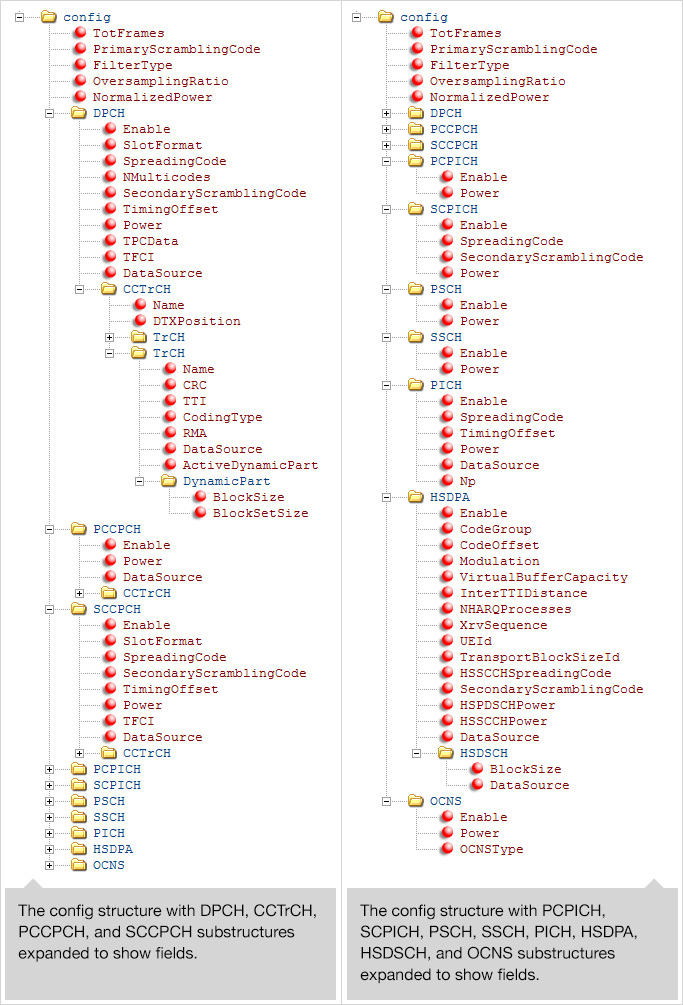
This image shows the downlink reference channel configuration structure fields. The left side of the figure expands the substructures to reveal fields in the top half of the structure. The right side of the figure expands the substructures to reveal fields in the bottom half of the structure.
Note
The single output data stream from the TrCH multiplexing, including the
downlink DTX indication bits, is denoted as the coded composite transport
channel (CCTrCH). A CCTrCH can be mapped to one or several physical channels.
Each physical channel substructure (DPCH,
PCCPH, and SCCPCH) can contain one
CCTrCH substructure which in turn contains one or more
TrCH substructures. Each CCTrCH
substructure is individually initialized and fully parameterizable. The general
TrCH coding and multiplexing and the CCTrCH processing are defined in TS 25.212,
Section 4.2 [3]. TS 25.302, Section 6 [4]
specifies C/I, the power control and duplex mode restrictions when mapping
multiple CCTrCH on a physical channel.
Note
Each instance of the CCTrCH substructure contains the same
fields, so the contents is only expanded in the first appearance the figure.
Uplink Reference Channel and Waveform Generation Parameter Structures
Defining an uplink waveform requires initialization of a handful of top-level
parameters and substructures associated with permissible channels. The top-level
parameters include TotFrames, ScramblingCode,
FilterType, OversamplingRatio, and
NormalizedPower. The channel substructures can include
combinations of these channels DPDCH, DPCCH,
HSUPA, and HSDPCCH. Each channel substructure
includes the fields necessary to specify the indicated channel. You only include and
initialize the individual channel substructures needed to generate desired waveform.
The umtsUplinkReferenceChannels function
outputs a configuration structure based on an input character vector argument, which
maps to one of the reference channels defined in these 3GPP standards:
You can generate waveform using umtsUplinkWaveformGenerator with an input configuration structure that you:
Initialize by calling
umtsUplinkReferenceChannels, specifying one of the predefined reference channels as an inputInitialize to one of the predefined reference channels as above, and adjust settings manually
Manually initialize complying with the structure defined as input to
umtsUplinkWaveformGenerator
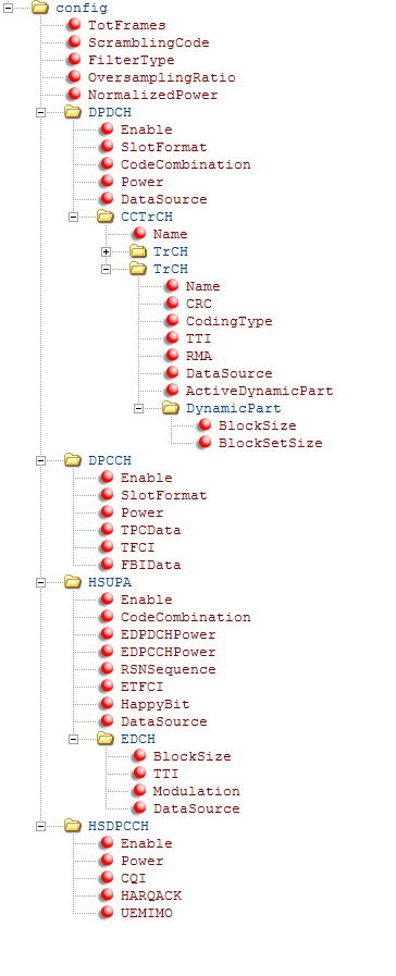
This image shows the uplink reference channel configuration structure.
Note
The single data stream output from the TrCH multiplexing is denoted as the
coded composite transport channel (CCTrCH). A CCTrCH can be mapped to one or
more physical channels. The DPDCH substructure can contain
one or more CCTrCH substructures. Each
CCTrCH substructure is individually initialized and fully
parameterizable. The general TrCH coding and multiplexing and the CCTrCH
processing are defined in TS 25.212, Section 4.2 [3]. TS25.302, Section 6 of [4]
specifies C/I, the power control and duplex mode restrictions when mapping
multiple CCTrCH on the physical channel.
References
[1] 3GPP TS 25.101. “Universal Mobile Telecommunications System (UMTS); User Equipment (UE) Radio Transmission and Reception (FDD).” 3rd Generation Partnership Project; Technical Specification Group Radio Access Network. URL: https://www.3gpp.org.
[2] 3GPP TS 25.141. “Universal Mobile Telecommunications System (UMTS); Base Station (BS) Conformance Testing (FDD).” 3rd Generation Partnership Project; Technical Specification Group Radio Access Network. URL: https://www.3gpp.org.
[3] 3GPP TS 25.212. “Universal Mobile Telecommunications System (UMTS); Multiplexing and channel coding (FDD).” 3rd Generation Partnership Project; Technical Specification Group Radio Access Network. URL: https://www.3gpp.org.
[4] 3GPP TS 25.302. “Universal Mobile Telecommunications System (UMTS); Services provided by the physical layer.” 3rd Generation Partnership Project; Technical Specification Group Radio Access Network. URL: https://www.3gpp.org.
See Also
umtsDownlinkWaveformGenerator | umtsUplinkReferenceChannels | umtsUplinkWaveformGenerator