Main Content

LTE Waveform Generator

Create, impair, visualize, and export LTE waveforms

Description

The LTE Waveform Generator app enables you to create, impair, visualize, and export LTE waveforms.

The app provides these capabilities by using the Wireless Waveform Generator app configured for LTE waveform generation. Using the app, you can:

  • Generate LTE test model (E-TM) waveforms, as defined in section 6 of TS 36.141 [1].

  • Generate LTE downlink reference measurement channel (RMC) waveforms for user equipment (UE) performance testing, as defined in Annex A.3 of TS 36.101 [2].

  • Generate LTE uplink RMC waveforms for base station (BS) performance testing, as defined in Annex A of TS 36.104 [3].

  • Export the LTE waveform to your workspace or to a .mat, .bb, or .txt file.

  • Export LTE waveform generation parameters to an executable MATLAB® script or a Simulink® block.

    • Use the exported script to generate your waveform without the app from the command line.

    • Use the exported block as a waveform source in a Simulink model. For more information, see Waveform From Wireless Waveform Generator App.

  • Visualize the LTE waveform in constellation diagram, spectrum analyzer, OFDM grid, 3D spectrogram, time scope, and complementary cumulative distribution function (CCDF) plots.

  • Distort the LTE waveform by adding RF impairments, such as AWGN, phase offset, frequency offset, DC offset, IQ imbalance, and memoryless cubic nonlinearity.

  • Generate an LTE waveform that you can transmit using a connected signal generator or software-defined radio (SDR).

To create, impair, visualize, and export waveforms other than LTE waveforms, you must reconfigure the app. For a full list of features, see the Wireless Waveform Generator app.

For more information, see Create Waveforms Using Wireless Waveform Generator App.

LTE Waveform Generator app

Open the LTE Waveform Generator App

MATLAB Toolstrip: On the Apps tab, under Signal Processing and Communications, click the app icon.

MATLAB Command Prompt: Enter wirelessWaveformGenerator. This command opens the Wireless Waveform Generator app. To configure the app for LTE waveform generation, in the Waveform Type section, select one of the options under LTE (4G).

Examples

expand all

This example shows how to generate LTE test model (E-TM) and reference measurement channel (RMC) waveforms by using the LTE Waveform Generator app.

Open LTE Waveform Generator App

On the Apps tab of the MATLAB® toolstrip, select the LTE Waveform Generator app icon under Signal Processing and Communications. This section opens the Wireless Waveform Generator app configured for LTE waveform generation.

Select LTE Waveform

Choose the waveform you want to generate by selecting one of the options under LTE (4G) in the Waveform Type section of the app toolstrip. The app supports these waveforms.

  • Downlink RMC

  • Uplink RMC

  • Test Models

Generate LTE Waveform

Set the parameters for the selected waveform by specifying options in the Waveform tab on the left pane of the app. Add impairments and select visualization tools by specifying options in the Generation section of the app toolstrip. To visualize the waveform, click Generate.

For example, this figure shows the visualization results of a downlink RMC waveform with default parameters.

Export Generated Waveform

You can export the generated waveform and its parameters by clicking Export. You can export the waveform to:

  • A MATLAB script with a .m extension, which you can run to generate the waveform without the app

  • A file with a .bb or .mat extension

  • Your MATLAB workspace as a structure

  • A Simulink® block, which you can use to generate the waveform in a Simulink model without the app

Transmit LTE Waveform

This feature requires Instrument Control Toolbox™ software. To transmit a generated waveform, click the Transmitter tab on the app toolstrip and configure the instruments. You can use any instrument supported by the rfsiggen (Instrument Control Toolbox) function.

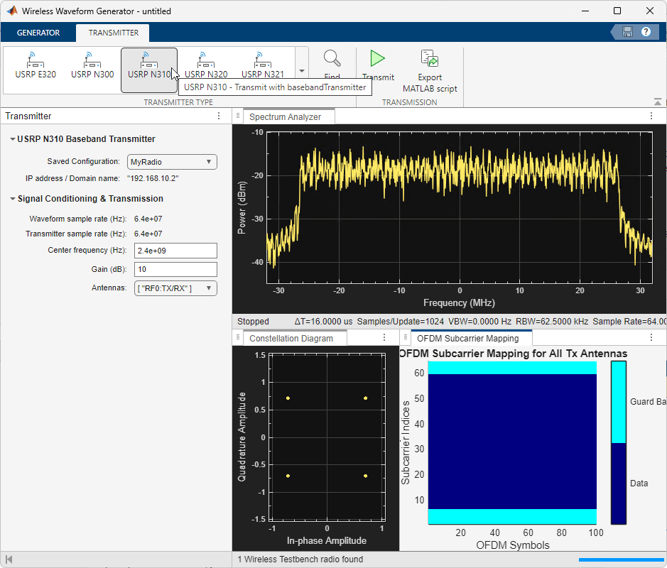
This example shows how to use the NI™ USRP™ N300, N310, USRP N320, USRP N321, USRP X300, X310, and USRP X410 radio transmitters available in the Wireless Waveform Generator app to transmit an app-generated waveform over the air (requires Wireless Testbench™). These radio transmitters enable you to transmit up to 2 GB of contiguous data over the air at the maximum baseband sample rate supported by the radio device.

Introduction

The Wireless Waveform Generator app is an interactive tool for creating, impairing, visualizing, and transmitting waveforms. Using a radio transmitter available in the app, you can transmit your generated waveform repeatedly over the air. You can also export the waveform generation and transmission parameters to a runnable MATLAB® script. This example shows how to configure these radio transmitters.

Although this example shows how to transmit an OFDM waveform, the same process applies for all waveform types that you can generate with the app.

Set Up for Radio Transmission

To use the radio transmitters in the app, you need to Install Support Package for NI USRP Radios (Wireless Testbench) and set up your radio using the Radio Setup (Wireless Testbench) wizard.

Generate Waveform for Transmission

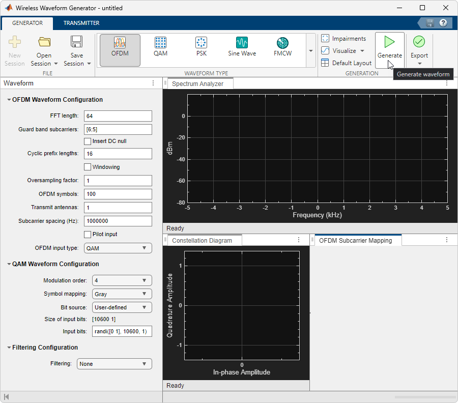
Open the Wireless Waveform Generator app by clicking the app icon on the Apps tab, under Signal Processing and Communications. Alternatively, enter wirelessWaveformGenerator at the MATLAB command prompt.

In the Waveform Type section, select an OFDM waveform by clicking OFDM. In the leftmost pane of the app, adjust any configuration parameters for the selected waveform. Then generate the configuration by clicking Generate in the app toolstrip.

Configure Radio Transmitter

Select the Transmitter tab from the app toolstrip. In the transmitter gallery, select a radio transmitter.

In the leftmost pane of the app, select the name of a radio setup configuration that you saved using the Radio Setup (Wireless Testbench) wizard.

Set the center frequency, gain, and antennas configuration parameters. The app automatically sets the waveform sample rate based on the waveform that you generated earlier. The radio transmitter uses onboard data buffering to ensure contiguous data transmission at up to the maximum baseband sample rate supported by the radio device. To achieve the specified sample rate, the radio uses a Farrow rate converter. If necessary, use this list as a reference when setting the sample rate:

  • USRP N300 -- 120,945 Hz to 76.8 MHz, or one of: 122.88 MHz, 125 MHz, or 153.6 MHz

  • USRP N310 -- 120,945 Hz to 76.8 MHz, or one of: 122.88 MHz, 125 MHz, or 153.6 MHz

  • USRP N320 -- 196,851 Hz to 125 MHz, or one of: 200 MHz, 245.76 MHz or 250 MHz

  • USRP N321 -- 196,851 Hz to 125 MHz, or one of: 200 MHz, 245.76 MHz or 250 MHz

  • USRP X300 -- 181,418 Hz to 100 MHz, or one of: 184.32 MHz or 200 MHz

  • USRP X310 -- 181,418 Hz to 100 MHz, or one of: 184.32 MHz or 200 MHz

  • USRP X410 -- 241,890 Hz to 125 MHz, or one of: 245.76 MHz or 250 MHz

Transmit Waveform

To transmit the waveform continuously, click Transmit. To end the continuous transmission, click Stop transmission. To export the waveform generation and transmission parameters to a runnable MATLAB script, click Export MATLAB script.

References

[1] 3GPP TS 36.141. “Base Station (BS) conformance testing.” 3rd Generation Partnership Project; Technical Specification Group Radio Access Network; Evolved Universal Terrestrial Radio Access (E-UTRA). https://www.3gpp.org.

[2] 3GPP TS 36.101. “Evolved Universal Terrestrial Radio Access (E-UTRA); User Equipment (UE) radio transmission and reception.” 3rd Generation Partnership Project; Technical Specification Group Radio Access Network. https://www.3gpp.org.

[3] 3GPP TS 36.104. “Evolved Universal Terrestrial Radio Access (E-UTRA); Base Station (BS) radio transmission and reception.” 3rd Generation Partnership Project; Technical Specification Group Radio Access Network. https://www.3gpp.org.
Version History

Introduced in R2019a

expand all

Go to top of page