Plate Condenser Evaporator (TL-2P)
Plate geometry condenser evaporator between two-phase fluid and thermal liquid networks
Since R2024a

Libraries:
Simscape /
Fluids /
Heat Exchangers /
Two-Phase Fluid - Thermal Liquid
Description
The Plate Condenser Evaporator (TL-2P) block models a plate heat exchanger between a thermal liquid and a two-phase fluid network. The block models the heat transfer between the thermal liquid and the two-phase fluid based on the effectiveness-NTU method. Heat transfer can occur in either direction between the two fluids.
The block uses the Effectiveness-NTU (E-NTU) method to model heat transfer through the shared plate walls. You can also account for heat transfer through the plate itself by selecting the Enable plate thermal resistance parameter. The block models fouling on the exchanger walls, which increases thermal resistance and reduces the heat exchange between the two fluids.
The two-phase fluid flows use a boundary-following model to track the subcooled liquid, vapor-liquid mixture, and superheated vapor in three zones. The relative amount of space a zone occupies in the system is called a zone fraction.
Plate Heat Exchanger Geometry
Plate heat exchangers consist of a series of clamped-together plates. Each plate has portholes for the fluid to flow through and gaskets around the portholes and the plate sides to contain the liquid. The gasket pattern alternates between the plates so that on each side of the plate, one fluid flows across the plate while the other fluid flows through it. This design results in alternating layers of hot and cold fluid. This figure shows a section of counter-flow in a plate heat exchanger.
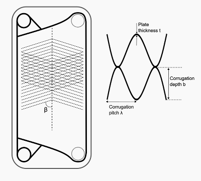
This figure shows an individual plate and a cross-section of two adjacent plates. In the individual plate image, the thick lines represent the gaskets and the dotted lines represent the plate corrugation. The block assumes that the flow channel gap between the plates equals the corrugation depth, b.
On this plate, one fluid flows from the top-right port hole across the plate to the bottom-right port hole. The other fluid flows through the gasket on the two left-side portholes and not touch the plate on this side. The plate corrugation patterns increase structural stiffness, surface area, and turbulence.
Because fluid flows along both sides of each plate, the total fluid volume is
where:
Np is the value of the Number of plates parameter.
Lp is the value of the Plate length parameter.
Wp is the value of the Plate width parameter.
b is the value of the Spacing between plates parameter.
The volume of each fluid is half of the total volume. The flow cross-sectional area, S, for each fluid is
The total projected surface area of the plates, assuming no corrugation, is
Each fluid has half of the total heat transfer surface area
where the area enlargement factor, ϕ, accounts for the increased surface area due to the corrugation
The hydraulic diameter for each fluid is
Effectiveness-NTU Heat Transfer
The block calculates the heat transfer rate in three parts to correspond with the with the three fluid zones that occur on the two-phase fluid side of the heat exchanger.
The convective heat transfer in a zone is
where:
CMin is the lesser of the heat capacity rates of the two fluids in that zone. The heat capacity rate is the product of the fluid specific heat, cp, and the fluid mass flow rate. CMin is always positive.
TIn,2P is the zone inlet temperature of the two-phase fluid.
TIn,TL is the zone inlet temperature of the thermal liquid.
ε is the heat exchanger effectiveness.
Effectiveness is a function of the heat capacity rate and the number of transfer units, NTU, and varies based on the heat exchanger flow arrangement. NTU is
where:
z is the individual zone fraction.
R is the total thermal resistance between the two flows due to convection, conduction, and any fouling on the plates:
where:
U is the convective heat transfer coefficient of the respective fluid.
F is the value of the Fouling factor parameter on the two-phase fluid or thermal liquid side.
RW is the thermal resistance through the plates. If you select Enable plate thermal resistance, where t is the value of the Plate thickness parameter and kp is the value of the Plate thermal conductivity parameter.
If you clear the Enable plate thermal resistance check box, RW = 0.
The total convective heat transfer rate between the fluids is the sum of the heat transferred in the three zones by the subcooled liquid, QL, liquid-vapor mixture, QM, and superheated vapor, QV,
The fluid properties that the block uses in heat transfer calculations are the average between the value at the inlet and the value in the fluid volume.
The heat exchanger effectiveness varies according to the flow configuration and fluid stage. The effectiveness is for all flow arrangements in the liquid-vapor mixture zone.
For the subcooled liquid and the superheated vapor zones, when Flow
arrangement is Parallel flow
For the subcooled liquid and the superheated vapor zones, when Flow
arrangement is Counter flow
CR is the ratio between the heat capacity rates of the two fluids
Conductive Heat Transfer
The conductive heat transfer in a zone is
where:
Tout,2P is the zone outlet temperature of the two-phase fluid.
Tout,TL is the zone outlet temperature of the thermal liquid.
Rcond is the total conductive thermal resistance between the two flows,
where:
AW is the wall surface area.
k is the thermal conductivity of each fluid.
DH is the hydraulic diameter.
The total heat transfer is the sum of the convective and conductive heat transfer. The conductive heat transfer is negligible compared to the convective heat transfer. When the flow rate is zero, the convective heat transfer is also zero. However, because heat transfer from convection and conduction operate independently of each other, there is still conductive heat transfer even when the convective heat transfer is zero.
Pressure Loss
For both fluids and pressure loss parameterizations, the pressure loss between each port and the internal node is
where:
ṁA is the mass flow rate through port A1 or A2 when the block calculates the values for the thermal liquid and two-phase networks, respectively.
ṁB is the mass flow rate through port A1 or A2 when the block calculates the values for the thermal liquid and two-phase networks, respectively.
ρ is the fluid density.
ξports is the value of the Loss coefficient for inlet and outlet manifolds and ports parameter.
Sport,A is the value of the Cross-sectional area at port A1 or Cross-sectional area at port A2 parameter, when the block calculates the values for the thermal liquid and two-phase networks, respectively.
Sport,B is the value of the Cross-sectional area at port B1 or Cross-sectional area at port B2 parameter, when the block calculates the values for the thermal liquid and two-phase networks, respectively.
When the Pressure loss model parameter is
Friction factor, you use the Darcy friction
factor for flow between corrugated plates parameter to specify a
single constant friction factor for the fluid.
fDarcy is the value of the
Darcy friction factor for flow between corrugated plates
parameter.
When the Pressure loss model parameter is
Correlation for flow between corrugated plates, the
block calculates the Darcy friction factor based on the plate geometry data and
Reynolds number from [3].
The Reynolds number is where μ is the dynamic viscosity. When the Reynolds number is between 200 and 1000,
When the Reynolds number is greater than 2000,
The block uses a smooth cubic transition between these regions and for Reynolds numbers between 1000 and 2000. For Reynolds numbers below 200, the block calculates fDarcy from a laminar friction constant that ensures numerical robustness as the flow goes to 0.
Heat Transfer Coefficient
The heat transfer coefficient, U, is
The heat transfer calculations depend on the value of the Heat transfer coefficient model parameter and the two-phase fluid zone. When the thermal liquid and two-phase fluid are in the subcooled liquid or superheated vapor zone, k is the fluid thermal conductivity. When the two-phase fluid is in the saturated liquid-vapor mixture zone, k is the saturated liquid thermal conductivity.
When Heat transfer coefficient model is
Colburn equation, the block calculates the heat
transfer coefficient from data by using the Colburn correlation
coefficients.
When the thermal liquid and two-phase fluid are in the subcooled liquid or superheated vapor zone, the Nusselt number is
where a, b, and c are the first, second, and third elements in the Coefficients [a, b, c] for a*Re^b*Pr^c parameter and Pr is the Prandtl number.
When the two-phase fluid is in the saturated liquid-vapor mixture zone, the Nusselt number from [2] is
where:
ReSL and PrSL are the Reynolds number and the Prandtl number of the saturated liquid, respectively.
vSL and vSV are the saturated liquid and vapor specific volumes, respectively.
xin is the vapor quality at the start of the saturated liquid-vapor mixture zone.
xout is the vapor quality at the end of the saturated liquid-vapor mixture zone.
When Heat transfer coefficient model is
Correlation for flow between corrugated plates,
the block calculates the heat transfer coefficient based on the plate geometry
data.
When the thermal liquid and two-phase fluid are in the subcooled liquid or superheated vapor zone, the Nusselt number from [3] is
where:
c1, c2, and c3 are the first, second, and third elements in the Coefficients for Martin correlation parameter.
Pr is the Prandtl number.
When the two-phase fluid is in the saturated liquid-vapor mixture zone, the Nusselt number from [2] is
Plate Thermal Mass
If you select Enable plate thermal mass, the block models the heat exchanger plate thermal mass, which introduces a delay in the plate's transient response to changes in temperature or heat flux. If you model thermal mass, the plate stores heat in its bounds. This heat storage slows the transition between steady states so that a thermal perturbation on one side does not immediately manifest on the other side. The lag persists until the heat flow rates from the two sides balance.
If you select Enable plate thermal mass, the wall energy conservation is
where:
Mplate is the mass of the plates, which the block calculates from the plate geometry parameters and the Plate density parameter.
cp,plate is the value of the Plate specific heat parameter.
Tplate is the effective plate temperature. The block uses this value to model the transient response. You cannot measure this value.
The heat transfer to each fluid is
where:
Tin is the fluid inlet temperature on each side.
C is the heat capacity rate for each fluid.
The number of heat transfer units between the fluid and the plate on each side is
where A is the total plate surface area and U is the heat transfer coefficient.
Conservation Equations
The total mass accumulation rate in the two-phase fluid is
where:
M2P is the total mass of the two-phase fluid.
A2 is the mass flow rate of the fluid at port A2.
B2 is the mass flow rate of the fluid at port B2.
The block relates the change in specific internal energy to the heat transfer by the fluid by using the equation
where:
u2P is the two-phase fluid specific internal energy.
φA1 is the energy flow rate at port A1.
φB1 is the energy flow rate at port B1.
Q is heat transfer rate.
The total mass accumulation rate in the thermal liquid is
The energy conservation equation is
where:
ϕA1 is the energy flow rate at port A1.
ϕB1 is the energy flow rate at port B1.
The heat transferred to or from the thermal liquid, Q, equals the heat transferred from or to the two-phase fluid.
Examples
This example uses the Plate Condenser Evaporator (TL-2P) block to model heat transfer between a thermal liquid and two-phase fluid network. The thermal liquid network is 300 K and the working fluid is water. The two-phase fluid is 280 K and the working fluid is propane.
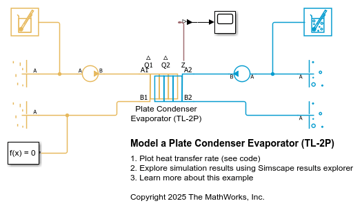
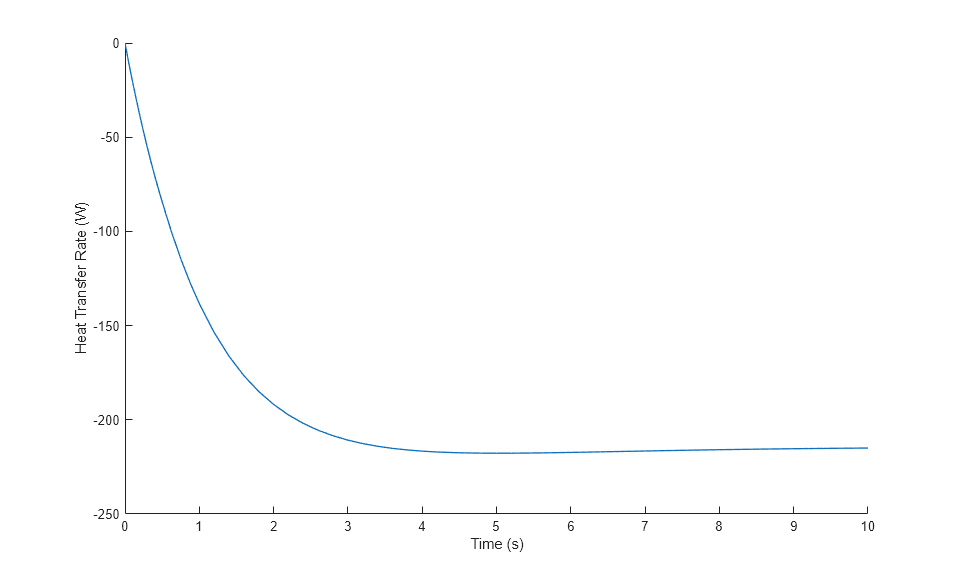
This figure shows the rate of heat transfer from the hot side to the cold side through the heat exchanger. The heat transfer from the cold side to the hot side is equal in magnitude, but positive. The heat transfer rate starts at 0 W because the initial temperatures on both sides of the heat exchanger are equal.
Ports
Output
Conserving
Parameters
Configuration
Flow path alignment across the heat exchanger. The available flow arrangements are:
Parallel flow— The flows run in the same direction.Counter flow— The flows run parallel to each other, in the opposite directions.
Number of plates in the heat exchanger. Fluid flows across both sides of each plate, including the end plate and start plate.
Length of each plate. This value is the longer side of the plate and the flow axis of the fluid.
Width of each plate.
Gap between each plate. This parameter value usually equals the corrugation depth.
Whether you specify the surface area enlargement factor directly or the block calculates the enlargement factor from a specified chevron geometry.
Multiplier that accounts for the increase in plate surface area due to corrugation. If each plate is perfectly flat, the value of this parameter is 1. Otherwise, this value is the ratio of the actual total surface area to the area of the two-dimensional projection of the plate shape.
Dependencies
To enable this parameter, set Corrugation pattern
specification to Surface area
enlargement factor.
Angle of the chevron corrugation on each plate. This value is β in this plate diagram:
Dependencies
To enable this parameter, set Corrugation pattern
specification to Chevron
geometry.
Ratio of the chevron corrugation depth to the corrugation pitch. The corrugation pitch is the corrugation wavelength. The value of this parameter is b/λ in this diagram:
Dependencies
To enable this parameter, set Corrugation pattern
specification to Chevron
geometry.
Option to model plate thermal resistance. If you select this check box, the block uses the values of the Plate thickness and Plate thermal conductivity parameters to calculate the thermal resistance through each plate. If you clear this check box, the block does not model the effects of thermal resistance through the plates.
Whether to model the plate thermal mass. Modeling the plate thermal mass introduces a delay in the transient response of the plate to changes in temperature or heat flux. If you clear Enable plate thermal mass, the block assumes that the plate is thin enough for the transient response to be instantaneous on the time scale of the heat transfer.
Thickness of each plate in the heat exchanger.
Dependencies
To enable this parameter, select Enable plate thermal resistance or Enable plate thermal mass.
Density of the plate. The block uses this value to calculate the plate thermal mass.
Dependencies
To enable this parameter, select Enable plate thermal mass.
Specific heat of the plate. The block uses this value to calculate the plate thermal mass.
Dependencies
To enable this parameter, select Enable plate thermal mass.
Thermal conductivity of each plate.
Dependencies
To enable this parameter, select Enable plate thermal resistance.
Flow area at the thermal liquid port A1.
Flow area at the thermal liquid port B1.
Flow area at the two-phase fluid port A2.
Flow area at the two-phase fluid port B2.
Thermal Liquid 1
Method of pressure loss calculation due to viscous friction for the thermal liquid. The settings are:
Friction factor— The block calculates the pressure loss based on a constant Darcy friction factor for flow between the plate passages, specified by the Darcy friction factor for flow between corrugated plates parameter.Correlation for flow between corrugated plates— The block uses the Martin correlation for plate heat exchangers with the chevron or herringbone pattern to calculate the pressure loss.
Constant Darcy friction factor to use to calculate the pressure loss.
If you have data for the pressure loss across the heat exchanger, Δpdata, and the mass flow rate through the heat exchanger, ṁdata, the value of this parameter is
If you do not have data for ξports, use the default value of the Loss coefficient for inlet and outlet manifolds and ports parameter in this expression. If you have multiple data points for Δpdata and ṁdata, use a least squares fit to find fdarcy.
If you know the loss coefficient value, ξloss, for your heat exchanger, then fDarcy = ξloss Dh / LP.
Dependencies
To enable this parameter, set Pressure loss
model to Friction
factor.
Pressure loss coefficient that accounts for losses at the inlet and outlet manifolds and ports on the thermal liquid side.
Method of calculating the heat transfer coefficient for the thermal fluid. The available settings are:
Colburn equation— Use this setting to calculate the heat transfer coefficient by defining the variables a, b, and c of the Colburn equation. Use this option to fit the heat transfer results to the experimental data by estimating the coefficients.Correlation for flow between corrugated plates— Use this setting to calculate the heat transfer coefficient based on the plate geometry data and the Martin correlation.
Three-element vector that contains the empirical coefficients of the Colburn equation. The Colburn equation is a formulation for calculating the Nusselt number.
Dependencies
To enable this parameter, set Heat transfer coefficient
model to Colburn
equation.
Three-element vector that contains the coefficients c1, c2, and c3 that the block uses to calculate the Nusselt number by using the Martin correlation:
Dependencies
To enable this parameter, set Heat transfer coefficient
model to Correlation for flow between
corrugated plates.
Additional thermal resistance due to fouling layers on the surfaces of the wall. In real systems, fouling deposits grow over time. However, the growth is slow enough that the block assumes the fouling is constant during the simulation.
Thermal liquid pressure at the start of the simulation.
Temperature in the thermal liquid channel at the start of the simulation. This parameter
can be a scalar or a two-element vector. A scalar value represents the
mean initial temperature in the fluid flow. A vector value represents
the initial temperature at the inlet and outlet in the form
[inlet, outlet]. The block
calculates a linear gradient between the two ports. The initial flow
direction determines the inlet and outlet ports.
Two-Phase Fluid 2
Method of pressure loss calculation due to viscous friction for the two-phase fluid. The settings are:
Friction factor— The block calculates the pressure loss based on a constant Darcy friction factor for flow between the plate passages, specified by the Darcy friction factor for flow between corrugated plates parameter.Correlation for flow between corrugated plates— The block uses the Martin correlation for plate heat exchangers with the chevron or herringbone pattern to calculate the pressure loss.
Constant Darcy friction factor to use to calculate the pressure loss.
If you have data for the pressure loss across the heat exchanger, Δpdata, and the mass flow rate through the heat exchanger, ṁdata, the value of this parameter is
If you do not have data for ξports, use the default value of the Loss coefficient for inlet and outlet manifolds and ports parameter in this expression. If you have multiple data points for Δpdata and ṁdata, use a least squares fit to find fdarcy.
If you know the loss coefficient value, ξloss, for your heat exchanger, then fDarcy = ξloss Dh / LP.
Dependencies
To enable this parameter, set Pressure loss
model to Friction
factor.
Pressure loss coefficient that accounts for losses at the inlet and outlet manifolds and ports on the thermal liquid side.
Method of calculating the heat transfer coefficient for the two-phase fluid. The available settings are:
Colburn equation— Use this setting to calculate the heat transfer coefficient by defining the variables a, b, and c of the Colburn equation. Use this option to fit the heat transfer results to the experimental data by estimating the coefficients.Correlation for flow between corrugated plates— Use this setting to calculate the heat transfer coefficient based on the plate geometry data and the Martin correlation.
Three-element vector that contains the empirical coefficients of the Colburn equation. Each fluid zone has a distinct Nusselt number, which the block calculates by using the Colburn equation in each zone. The general form of the Colburn equation is:
Dependencies
To enable this parameter, set Heat transfer coefficient
model to Colburn
equation.
Three-element vector that contains the coefficients for the Longo correlation. The block uses the Longo correlation to calculate the Nusselt number in the mixture zone.
Dependencies
To enable this parameter, set Heat transfer coefficient
model to Colburn
equation.
Three-element vector that contains the empirical coefficients of the Colburn equation. Each fluid zone has a distinct Nusselt number, which the block calculates by using the Colburn equation in each zone. The general form of the Colburn equation is:
Dependencies
To enable this parameter, set Heat transfer coefficient
model to Colburn
equation.
Three-element vector that contains the coefficients c1, c2, and c3 that the block uses to calculate the Nusselt number by using the Martin correlation in the liquid zone:
Dependencies
To enable this parameter, set Heat transfer coefficient
model to Correlation for flow between
corrugated plates.
Three-element vector that contains the coefficients for the Longo correlation. The block uses the Longo correlation to calculate the Nusselt number in the mixture zone.
Dependencies
To enable this parameter, set Heat transfer coefficient
model to Correlation for flow between
corrugated plates.
Three-element vector that contains the coefficients c1, c2, and c3 that the block uses to calculate the Nusselt number by using the Martin correlation in the vapor zone:
Dependencies
To enable this parameter, set Heat transfer coefficient
model to Correlation for flow between
corrugated plates.
Additional thermal resistance due to fouling layers on the surfaces of the wall. In real systems, fouling deposits grow over time. However, the growth is slow enough that the block assumes the fouling is constant during the simulation.
Quantity used to describe the initial state of the fluid.
The value for Initial fluid energy specification parameter limits the available initial states for the two-phase fluid. When Initial fluid energy specification is:
Temperature— Specify an initial state that is a subcooled liquid or superheated vapor. You cannot specify a liquid-vapor mixture because the temperature is constant across the liquid-vapor mixture region.Vapor quality— Specify an initial state that is a liquid-vapor mixture. You cannot specify a subcooled liquid or a superheated vapor because the liquid mass fraction is 0 and 1, respectively, across the whole region. Additionally, the block limits the pressure to below the critical pressure.Vapor void fraction— Specify an initial state that is a liquid-vapor mixture. You cannot specify a subcooled liquid or a superheated vapor because the liquid mass fraction is 0 and 1, respectively, across the whole region. Additionally, the block limits the pressure to below the critical pressure.Specific enthalpy— Specify the specific enthalpy of the fluid. The block does not limit the initial state.Specific internal energy— Specify the specific internal energy of the fluid. The block does not limit the initial state.
Fluid pressure at the start of the simulation.
Temperature in the two-phase fluid channel at the start of simulation. This parameter
can be a scalar or a two-element vector. A scalar value represents the
mean initial temperature in the channel. A vector value represents the
initial temperature at the inlet and outlet in the form
[inlet, outlet]. The block
calculates a linear gradient between the two ports. The initial flow
direction determines the inlet and outlet ports.
Dependencies
To enable this parameter, set Initial fluid energy
specification to
Temperature.
Vapor mass fraction in the two-phase fluid channel at the start of simulation. This
parameter can be a scalar or a two-element vector. A scalar value
represents the mean initial vapor quality in the channel. A vector value
represents the initial vapor quality at the inlet and outlet in the form
[inlet, outlet]. The block
calculates a linear gradient between the two ports. The initial flow
direction determines the inlet and outlet ports.
Dependencies
To enable this parameter, set Initial fluid energy
specification to Vapor
quality.
Vapor volume fraction in the two-phase fluid channel at the start of simulation. This
parameter can be a scalar or a two-element vector. A scalar value
represents the mean initial void fraction in the channel. A vector value
represents the initial void fraction at the inlet and outlet in the form
[inlet, outlet]. The block
calculates a linear gradient between the two ports. The initial flow
direction determines the inlet and outlet ports.
Dependencies
To enable this parameter, set Initial fluid energy
specification to Vapor void
fraction.
Enthalpy per unit mass in the two-phase fluid channel at the start of simulation. This
parameter can be a scalar or a two-element vector. A scalar value
represents the mean initial specific enthalpy in the channel. A vector
value represents the initial specific enthalpy at the inlet and outlet
in the form [inlet, outlet]. The
block calculates a linear gradient between the two ports. The initial
flow direction determines the inlet and outlet ports.
Dependencies
To enable this parameter, set Initial fluid energy
specification to Specific
enthalpy.
Internal energy per unit mass in the two-phase fluid channel at the start of simulation.
This parameter can be a scalar or a two-element vector. A scalar value
represents the mean initial specific internal energy in the channel. A
vector value represents the initial specific internal energy at the
inlet and outlet in the form [inlet,
outlet]. The block calculates a linear gradient
between the two ports. The initial flow direction determines the inlet
and outlet ports.
Dependencies
To enable this parameter, set Initial fluid energy
specification to Specific internal
energy.
References
[1] Shah, Ramesh K., and Dusan P. Sekulic. Fundamentals of heat exchanger design. John Wiley & Sons, 2003.
[2] Longo, Giovanni A., Giulia Righetti, and Claudio Zilio. "A new computational procedure for refrigerant condensation inside herringbone-type Brazed Plate Heat Exchangers." International Journal of Heat and Mass Transfer 82 (2015): 530-536.
[3] Martin, Holger. "A theoretical approach to predict the performance of chevron-type plate heat exchangers." Chemical Engineering and Processing: Process Intensification 35.4 (1996): 301-310.