Generate UVM Framework Testbench for Block-Level Verification
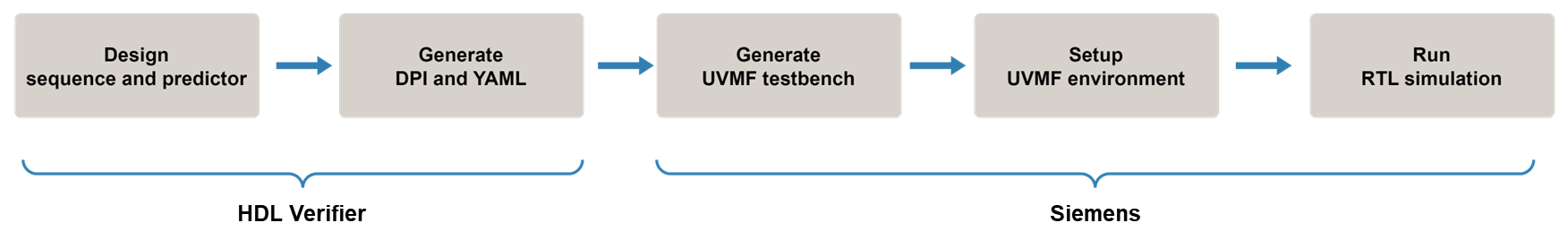
This example shows how to generate DPI components for a UVM sequence and predictor, and integrate them into a UVM framework (UVMF) testbench for block-level verification. The workflow follows these steps:
Design the sequence and predictor components in MATLAB® or Simulink®.
Generate DPI components and a UVMF-compliant YAML file using HDL Verifier™.
Generate testbench code using Siemens® UVMF tools.
Run RTL simulations using the Questa® simulator and perform block-level verification.
Using MATLAB or Simulink to autogenerate testbench components significantly reduces the time you need for manual testbench development.
Introduction
The UVMF is an open-source package from Siemens that provides a code generator to create infrastructure for UVM-based verification testbenches. For details, see the documentation included with the UVMF installation. You can download the UVMF software from the Siemens Verification Academy website.
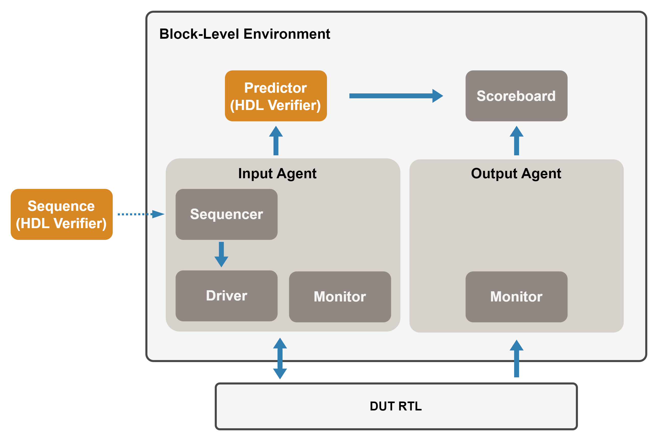
The objective of this example is to verify DUT RTL using a UVMF-generated testbench. The diagram below illustrates the architecture of a UVMF testbench:
Input agent — An active agent that drives test vectors into the DUT's input interface. The driver interfaces match the MATLAB or Simulink interfaces.
Output agent — A passive agent that monitors the design output interface and transfers the signal information to the scoreboard.
Predictor — A component that uses DPI code generated from MATLAB or Simulink to predict the outputs. This component sends the predicted outputs to the scoreboard.
Sequence — A component that uses DPI code generated from MATLAB or Simulink to generate the stimulus.
Scoreboard — A component that compares the actual and expected design outputs received from the output agent and predictor. It generates a UVM error if a comparison mismatch occurs.
The workflow for verifying a DUT using a UVMF testbench is as follows: First, design the sequence and predictor in MATLAB or Simulink, and generate the DPI and YAML files using HDL Verifier tools. Then, generate testbench code using UVMF tools and run the RTL simulations using the Questa simulator.
Overview of Design and Script Files
This example uses the following design and script files:
adder.v— DUT HDL file, representing a 16-bit adder. Your DUT can include multiple Verilog or SystemVerilog files. For the requirements of the HDL DUT, see Prepare DUT for UVM Framework Generation.helperExecuteUVMFShellScripts.m(located in thescriptsfolder) —Helper function that executes shell scripts after you generate the UVMF testbench.helperUpdateEnvironmentVariables.m(located in thescriptsfolder) — Helper function that updates UVMF environment variables after you generate the UVMF testbench.adder.m,adder_stimgen.m(located in theuvmf_matlabfolder) — MATLAB files for the predictor and sequence, respectively.MyAdder.slx(located in theuvmf_simulinkfolder) — Simulink model containing the sequence and predictor subsystems.
You can generate YAML files from MATLAB or Simulink on both Windows® and Linux® platforms. This example follows the workflow for Linux.
To save the existing working directory and set the necessary environment variables, execute the following commands:
UVMF_HOME – Set this environment variable to the installation path of the UVMF. For supported versions, see UVM and DPI Component Generation Requirements.
MTI_VCO_MODE– Set this environment variable to 64 to use the 64-bit Questa executable for UVMF testbench simulations.
workDir = pwd;
addpath("./scripts");

setenv("UVMF_HOME","/home/Documents/UVMF_2023.4_2");
setenv("MTI_VCO_MODE","64");
You can develop the predictor and sequence components using either MATLAB or Simulink. This example first outlines the MATLAB workflow, followed by the Simulink workflow.
Generate and Run UVMF Testbench from MATLAB
Design Predictor and Sequence Components in MATLAB
Run these commands to open the predictor function adder.m and the sequence function adder_stimgen.m. The behavior of the predictor function matches the RTL implementation of the DUT. The sequence function uses a 16-bit free-running counter as the stimulus for both the predictor and the DUT.
cd(fullfile(workDir,"uvmf_matlab"));

edit("adder.m");
edit("adder_stimgen.m");
Follow these guidelines when designing the predictor and the sequence components in MATLAB:
The predictor function name must match the DUT top module name.
The predictor function's input and output argument names must match the DUT top module's input and output port names.
The predictor function's input argument names must match the sequence function's output argument names.
Generate DPI Components and YAML from MATLAB
Run these commands to generate the predictor and sequence DPI code and UVMF testbench YAML. The script first creates svdpiConfiguration objects for the sequence and predictor, then creates a uvmfTestBenchConfiguration object to generate the UVMF testbench YAML file and DPI component files:
seq = svdpiConfiguration("uvmf-sequence");
seq.MATLABFunctionName = "adder_stimgen";

pred = svdpiConfiguration("uvmf-predictor");
pred.MATLABFunctionName = "adder";
pred.InputArgs = {uint16(0),uint16(0)};

uvmfObject = uvmfTestBenchConfiguration({pred, seq});
generateYAMLforUVMFTestBench(uvmfObject);
Generate UVMF Testbench Code
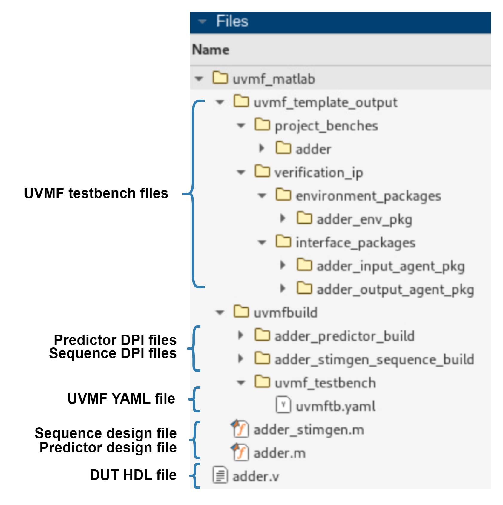
To generate the UVMF testbench, run the yaml2uvmf.py script (provided by UVMF tools), and use the generated YAML file as the input argument. The generated UVMF testbench is in the uvmf_template_output folder:
system("$UVMF_HOME/scripts/yaml2uvmf.py ./uvmfbuild/uvmf_testbench/uvmftb.yaml");This figure shows the generated artifacts.
Set Up Simulation Environment
UVMF generates shell scripts postfixed with *_mtlb_prep.sh. You can use these scripts to integrate the DPI components generated by HDL Verifier into the UVMF testbench. Run the following command to automate the execution of these scripts, using the path to the uvmf_template_output folder as an input argument:
helperExecuteUVMFShellScripts("./uvmf_template_output");Run the following command to set the environment variables required for Questa simulation. This helper script also saves the environment variables to the uvmf_template_output/project_benches/adder/sim/setup_adder_environment_variables.source file. You can source this file from a Linux terminal if you wish to run the RTL simulation again without starting MATLAB. Use the predictor DPI name and the sequence DPI name as the first and second input arguments, and use a cell array of DUT files as the third input argument.
helperUpdateEnvironmentVariables("adder", "adder_stimgen", {'../adder.v'});
For more information about this setup script, see the "Set Environment Variables in Generated Setup Script" section of the Integrate SystemVerilog DPI into UVM Framework Workflow example.
Run RTL Simulations
Navigate to the testbench sim folder. Run the make system command to execute the RTL simulations in Questa.
cd ./uvmf_template_output/project_benches/adder/sim;
system("make debug TEST_NAME=DPI_stimgen_test");
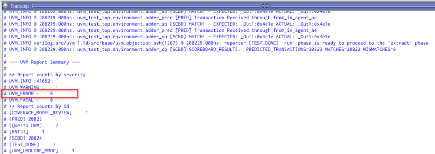
In Questa, enter run -all in the Transcript window. After the simulation, the Transcript window displays the UVM Report Summary.
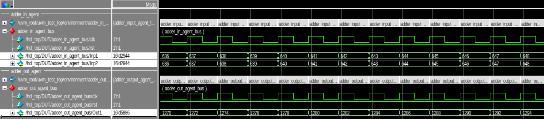
Open the Wave window to inspect the time diagram of the simulation results.
Generate and Run UVMF Testbench from Simulink
Design Predictor and Sequence Components in Simulink
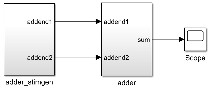
Run these commands to open the model containing the sequence and the predictor subsystem. The behavior of the predictor subsystem MyAdder/adder matches the RTL implementation of the DUT. The sequence subsystem MyAdder/adder_stimgen uses a 16-bit free-running counter block as the stimulus.
cd(fullfile(workDir,"uvmf_simulink"));
open_system("MyAdder");
Follow these guidelines when designing the predictor and the sequence components in Simulink:
The predictor subsystem name must match the DUT top module name.
The predictor subsystem input and output port names must match the DUT top module input and output port names.
The predictor subsystem input port names must match the sequence subsystem output port names.
Generate DPI Components and YAML from Simulink
Run the following commands to generate the predictor and the sequence DPI code and UVMF testbench YAML:
uvmfbuild(Predictor= "MyAdder/adder",Sequence= "MyAdder/adder_stimgen");
Generate UVMF Testbench Code
Run the yaml2uvmf.py script (provided by UVMF tools), and use the generated YAML file as the input argument. The generated UVMF testbench is in the uvmf_template_output folder:
system("$UVMF_HOME/scripts/yaml2uvmf.py ./uvmfbuild/uvmf_testbench/uvmftb.yaml");Set Up Simulation Environment
Run the following commands to automate the execution of shell scripts and set the environment variables. This setup is the same as the setup for the MATLAB workflow.
helperExecuteUVMFShellScripts("./uvmf_template_output");
helperUpdateEnvironmentVariables("adder", "adder_stimgen", {'../adder.v'});
Run RTL Simulations
Navigate to the testbench sim folder. Run the make system command to execute the RTL simulations in Questa.
cd ./uvmf_template_output/project_benches/adder/sim;
system("make debug TEST_NAME=DPI_stimgen_test");
In Questa, enter run -all in the Transcript window. After the simulation, the Transcript window displays the UVM Report Summary.
See Also
Topics
Select a Web Site
Choose a web site to get translated content where available and see local events and offers. Based on your location, we recommend that you select: United States.
You can also select a web site from the following list
Americas
- América Latina (Español)
- Canada (English)
- United States (English)
Europe
- Belgium (English)
- Denmark (English)
- Deutschland (Deutsch)
- España (Español)
- Finland (English)
- France (Français)
- Ireland (English)
- Italia (Italiano)
- Luxembourg (English)
- Netherlands (English)
- Norway (English)
- Österreich (Deutsch)
- Portugal (English)
- Sweden (English)
- Switzerland
- United Kingdom (English)