Generate Code Using Symbolic Dimensions for Flexible Signal Sizes
Symbolic dimensions in Simulink® represent signal dimensions in the model. Instead of using fixed numerical values for dimensions when building a model, you use symbols. Wherever you need to specify a signal dimension (such as for blocks and data objects), you can use symbolic dimensions instead of numerical values.
For a model with symbolic dimensions, Simulink propagates the symbolic dimensions throughout the diagram. When you generate code using Embedded Coder®, the generated code includes the symbolic dimensions in preprocessor conditionals, which makes the code flexible and able to work with different dimensions without having to regenerate the code. For more information on creating a model with symbolic dimension, see Create a Model with Symbolic Dimensions.
Storage Classes for Symbolic Dimensions
To implement symbolic dimensions, create a Simulink.Parameter object that represents a symbolic dimension in the base
workspace or a data dictionary. For successful code generation, the
Simulink.Parameter object must have one of these storage classes:
Define, ImportedDefinewith header file specifiedUser-defined custom storage class that defines data as a macro in a specified header file
For Simulink.Parameter objects with an
ImportedDefine custom storage class, ensure the header file is on the
MATLAB path. Enter the name of the header file in the HeaderFile
box in the Simulink.Parameter dialog box.
For more information on storage classes, see Choose Storage Class for Controlling Data Representation in Generated Code.
Generate C Code with Symbolic Dimensions
Before generating code for a model with symbolic dimensions, make sure that the simulation is successful. Simulink blocks vary in their ability to process symbolic dimensions. Some blocks can handle symbolic dimensions, while others produce an error. Unsupported blocks can still work in a model containing symbolic dimensions as long as they do not interact with symbolic dimensions.
Tip
To identify Simulink blocks that support symbolic dimension feature, enter
showblockdatatypetable in the MATLAB command prompt and check the
Block Support Table.
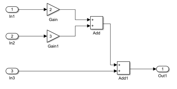
Example Model
You define the signal dimensions for the inport and outport block signals as symbolic dimensions in this example.
Define Symbolic Dimensions
Create a
Simulink.ParameterobjectSin the base workspace.S = Simulink.Parameter;
Set the signal dimension size of
Sto 3 using theValuefield and the data type todouble.S.Value = 3; S.DataType = "double";
Open the Block parameters dialog box for the inport block
In1. By default, the Port dimensions parameter is set to-1, indicating that the port inherits dimensions from the connected signal. Set Port dimensions parameter with the symbolic dimensionS. Similarly, change Port dimensions ofIn2,In3, andOut1toS.In the Debug tab, in the Diagnostics section, select Information Overlays > Signal Dimensions.
Simulate the model. Observe that Simulink propagates the symbolic dimensions throughout the diagram.
Generate Code
To generate code for this model, open the Embedded Coder app.
In the Code Mappings editor, under the Parameters tab, set the storage class of
StoCompilerFlag. For more information, see Storage Class Properties.To specify the symbolic dimension when building the code from Embedded Coder. In the Configuration Parameters dialog box, in the Code Generation>Custom Code pane, select the Code information tab and enter
S=3in the Defines box. Click OK. See Code Generation Pane: Custom Code: Additional Build Information: Defines.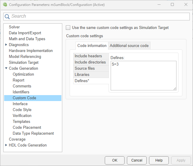
On the C Code tab, click Build.
The code generator creates the folder
model_name_ert_rtwin your current working folder and places source code files in that folder.View the generated code. In the
model_name.h, symbolic dimensions are defined for inports and outport blocks.typedef struct { real_T In1[S]; /* '<Root>/In1' */ real_T In2[S]; /* '<Root>/In2' */ real_T In3[S]; /* '<Root>/In3' */ } ExtU_slexVariantDimension_T; typedef struct { real_T Out1[S]; /* '<Root>/Out1' */ } ExtY_slexVariantDimension_T;The array sizes for inports and outport blocks are defined with the symbolic dimension size
S.In the
model_name.c, symbolic dimensions are used in loop bound calculations.void slexVariantDimension_step(void) { int32_T i; for (i = 0; i < S; i++) { slexVariantDimension_Y.Out1[i] = (2.0 * slexVariantDimension_U.In1[i] + 3.0 * slexVariantDimension_U.In2[i]) + slexVariantDimension_U.In3[i]; }