Create a Model with Symbolic Dimensions
This example shows how to use symbolic dimensions in a Simulink® model to design one model for many variants of a system that differ in signal dimensions.
Wherever you need to specify a signal dimension in your model, you can use symbolic dimensions instead of numerical dimensions, which provides flexibility for changing signal dimensions. Instead of altering the signal attribute to change the dimension, you use symbolic dimensions to make the change.
To implement symbolic dimensions, you create an object of Simulink.Parameter
If you have an AUTOSAR Blockset™ product license, you can also use AUTOSAR.Parameter (AUTOSAR Blockset)
Design Model
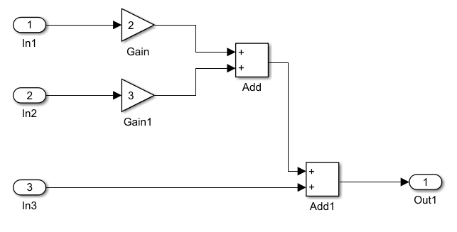
Create a model with three inports and one outport block using Gain and Add blocks as demonstrated.
Define Symbolic Dimensions
Create a Simulink.Parameter object S in the base workspace to represent the symbolic dimension.
S = Simulink.Parameter;
Set the symbolic dimension size and data type.
S.Value = 3;
S.DataType = "double";
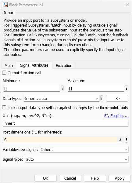
Open the Block Parameters dialog box for the inport block In1. By default, Port dimensions parameter is set to -1, indicating that the port inherits dimensions from the connected signal. Set Port dimensions to the symbolic dimension S.
Similarly, change Port dimensions of In2, In3, and Out1 to the symbolic dimension S.
In the Debug tab, in the Diagnostics section, select Information Overlays > Signal Dimensions. Simulate the model.
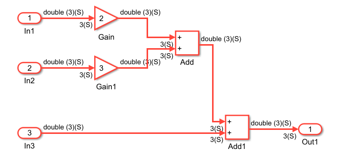
During simulation, Simulink propagates the symbolic signal dimension, set to 3, throughout the diagram.
Change Signal Dimensions
To change the signal dimensions without updating each signal attribute individually, specify the new dimension value in the Simulink.Parameter object S and simulate the model again.
S.Value = 4;
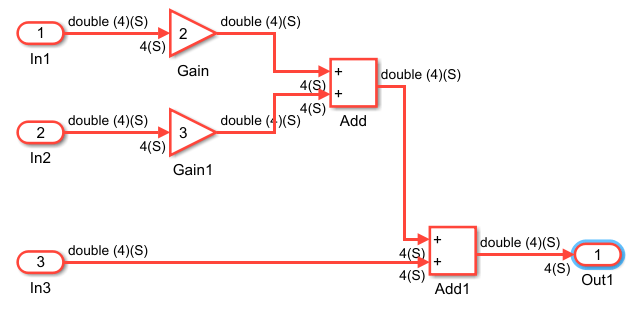
You can adjust the dimension value of S to a different size and observe how the new dimensions propagate during simulation. The Diagnostic Viewer shows a warning if there are any discripencies with the dimensions during signal propagation.
Symbolic dimension specification is enabled by default. To disable it, clear the Allow symbolic dimension specification parameter in the Configuration Parameters dialog box.
Simulink Blocks That Support Variant Signal Dimensions
Simulink blocks vary in their ability to process symbolic dimensions. Some blocks can handle symbolic dimensions, while others may produce an error. Unsupported blocks (for example, MATLAB Function blocks) can still work in a model containing symbolic dimensions as long as they do not directly interact with the symbolic dimensions.
The Simulink Block Data Type Support table includes a column identifying the blocks with symbolic dimension support.
In the MATLAB® command line, enter
showblockdatatypetable. A separate window with the Simulink Block Data Type Support table opens.In the Block column, locate the name of a Simulink block. An X in the symbolic dimension support column indicates that the block supports symbolic dimension propagation.