Prepare Models for Code Generation
Before you generate code, design your models to align with how you intend to deploy the generated code. Consider the organization of the model hierarchy, the storage of data required by the models, and modeling patterns that relate to the generated code. Check that your models are ready for code generation by applying the relevant modeling guidelines. To minimize rework, construct models by considering these code generation goals from the beginning of the design process.
Examine the Model Hierarchy
Organize the model hierarchy to represent the architecture of the code that you want to generate and to facilitate efficient and robust system development. This example shows common modeling techniques for code generation. You can also consider using the model components described in Compare Capabilities of Simulink Components and check your model against the Modeling Guidelines for Generated Code.
For this example, open the top model EvPowertrainController.
open_system("EvPowertrainController")Top Model: Software Component or Application
From a top model, the code generator generates a unit of code for use in a target execution environment. This top model represents a controller for the powertrain of an electric vehicle.
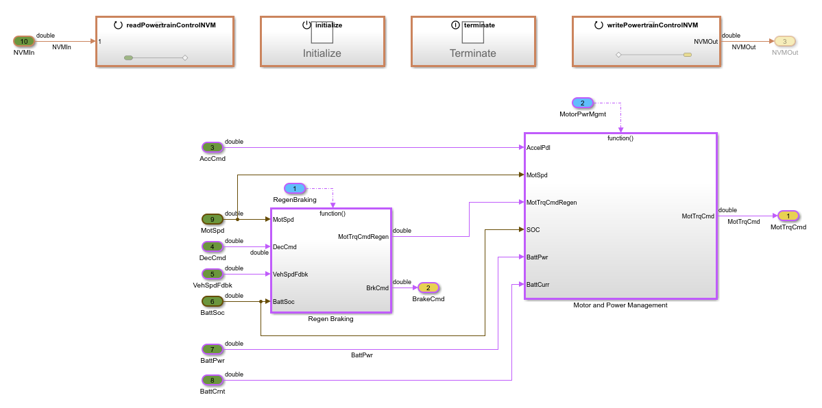
In this example, the top model represents a software component, which can run alongside other components in a single-process target environment. The other option for a top model is to represent an application, which can run in a single-process or multiprocess target environment.
Modeling Style: Export-Function or Rate-Based Modeling
Examine the modeling style of the top model. A model can use either rate-based modeling, which supports only a single rate, or export-function modeling, which supports single and multiple rates. The model EvPowertrainController uses export-function modeling, which means that it generates code for independent functions that you integrate in an external environment and scheduler.
In EvPowertrainController, these subsystems represent the generated functions:
InitializeTerminateReadPowertrainControlNVMWritePowertrainControlNVMRegen BrakingMotor and Power Management
For more information, see Export-Function Models Overview and Generate Code from Rate-Based Model.
Model Referencing
In the Model Browser panel, navigate to the node EvPowertrainController > Motor and Power Management > Battery Management System. The top model contains this Model reference block, which references the model BatteryManagementSystem.slx.
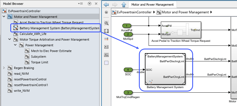
The code generator deploys referenced models such as this one as subcomponents of the parent component or application code. By using a referenced model for some functionality in the system, you can produce and test the referenced model independently of the top model. You can also easily reuse the referenced model functionality in other component models.
For more information about component-based modeling, see Component-Based Modeling in Simulink.
Shared Library Blocks
Navigate into the Regen Braking > Regen Braking control > Series Regen Braking subsystem. The subsystem contains two instances of the linked library subsystem BrakeConstant, which is saved in the library ControllerLibrary.slx.
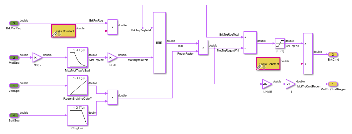
You can generate reusable shared utility code by using reusable subsystems such as the Brake Constant subsystem in this example. You can reuse the subsystems throughout your models and reuse the code generated from the subsystems by storing commonly used subsystems in a shared library.
For more information about sharing library blocks, see Create Custom Library.
Prepare Data Required by the Models
Organize the data that your models use according to your model architecture and the required visibility of the data. For this example, examine the different locations of data that the models use.
For more information about the options for storing and sharing data, see Determine Where to Store Variables and Objects for Simulink Models.
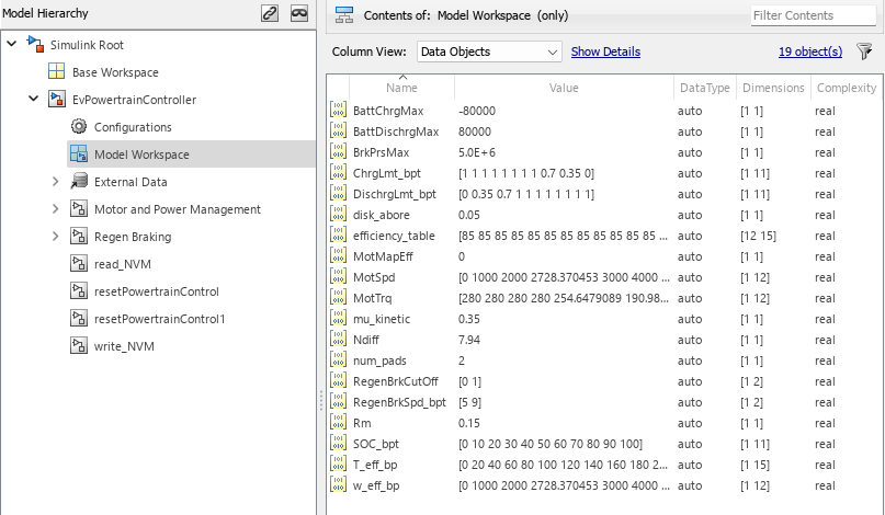
Model Workspace
On the Modeling tab, in the Design gallery, click Model Workspace. The model workspace stores variables that are visible only in the scope of the model, which establishes data ownership and improves model portability. When you reference a model multiple times, each instance of that model uses the same data from the model workspace by default, unless you configure the reference to use instance-specific parameters, as shown in Instance-specific Parameters for Referenced Models.
Data Dictionary
Examine data in the Simulink® data dictionary linked to the model, evModelingData.sldd. In the left pane of the Model Explorer, navigate to the EvPowertrainController > External Data > evModelingData > Design Data node.
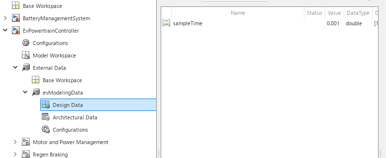
The data dictionary stores data that is shared among multiple models in the system, which are linked to the dictionary. Each model that is linked to the dictionary, including each instance of a model that is referenced multiple times, uses the same design data that is defined in the dictionary. For this example, design data is the variable sampleTime.
For more information about data dictionaries, see What Is a Data Dictionary?.
Instance-Specific Parameters for Referenced Models
From EvPowertrainController, navigate into the Motor and Power Management subsystem. The subsystem contains a Model reference block called Battery Management System, which refers to the model BatteryManagementSystem.slx. The reusable referenced model takes parameter values as model arguments, which you specify for each instance of the model referenced by a top model. This parameterization method enables you to specify different parameter values each time you reference the model.
Right-click the Model reference block, and then click the Block Parameters button ![]() . In the Block Parameters dialog box, on the Instance parameters tab, the table shows the instance-specific parameters of the referenced model.
. In the Block Parameters dialog box, on the Instance parameters tab, the table shows the instance-specific parameters of the referenced model.
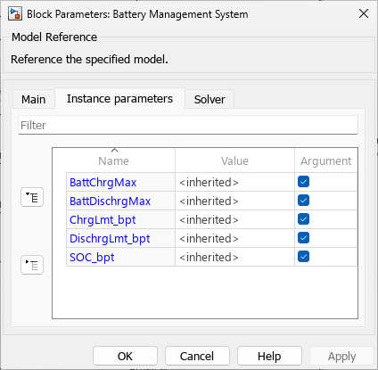
The instance-specific parameters include the battery charge and discharge maximums and lookup table data that provides charge and discharge limit breakpoints. For this example, the block uses the inherited values from the default values specified by BatteryManagementSystem.slx.
For more information, see Configure Instance-Specific Values for Block Parameters in a Referenced Model.
Testing Data
Examine the files in the current directory. The MAT files EvPowertrainController_inputs.mat and EvPowertrainController_outputs.mat store input and output data for the model EvPowertrainController. You use this data to test the model and the generated code.
Other Model Development Steps
During the model-based design process, you can perform additional tasks to prepare the models for code generation. Performing these steps before generating code can help you find and address design issues earlier in the design process and avoid some issues when you generate code.
Link design elements to requirements so that you can validate the design against the requirements.
Assess the models for design errors and compliance with modeling guidelines.
Perform simulation-based testing of the models.
Iterate and refine the model to meet your requirements.
For more information, see Model-Based Design with Simulink and Verification, Validation, and Test.