Communicate with Hardware Using Connected IO
You can use Connected IO to communicate with the IO peripherals on the hardware during simulation.
Simulation with Connected IO is an intermediate step in the Model-Based Design workflow. It bridges the gap between simulation and code generation by enabling Simulink® to communicate with the hardware before you deploy the model on the hardware. Connected IO enables you to modify your model design and monitor the effect of the modified design using the peripheral data from the hardware in a near real-time environment. You are not required to deploy the model on the hardware to monitor the effect of the modified design, which accelerates the simulation process.
These sections explain:
How to Enable Connected IO
To simulate a model in Connected IO, perform the following steps:
Open a Simulink model.
Press CTRL+E to open the Configuration Parameters dialog box.
In the Configuration Parameters dialog box, select Hardware Implementation.
Set the Hardware board parameter to any STM32 based board listed in the Supported STM32 Processor Based Boards section. This selection automatically populates the parameters in the Hardware board settings with the default values for the Discovery hardware.
From the Groups list under Target hardware resources, select Connectivity.
Select the Show serial configurations option and then specify the port to which the board is connected, for example,
COM1.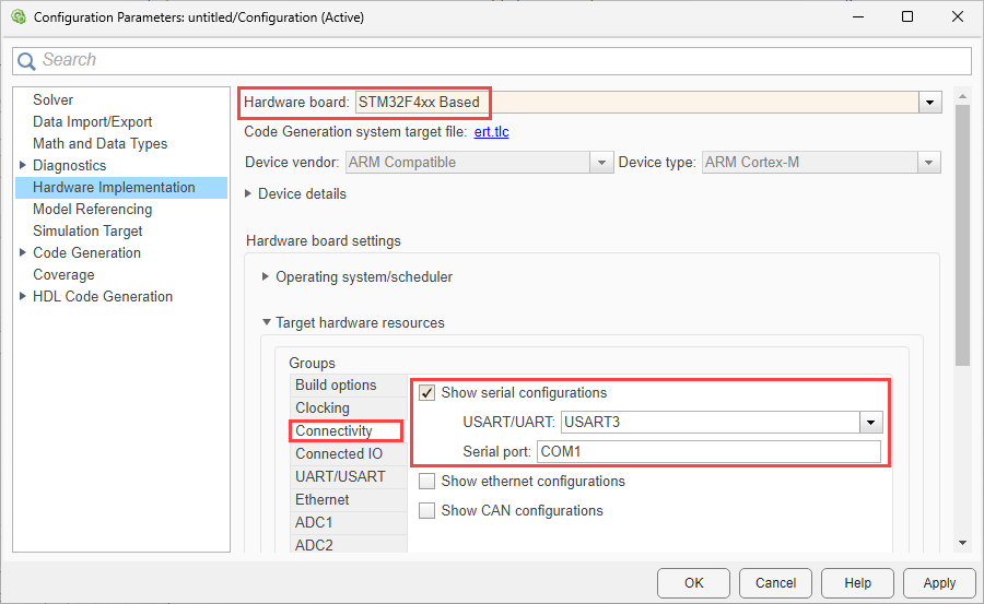
Click Apply. Click OK to close the dialog box.
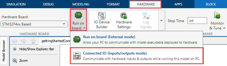
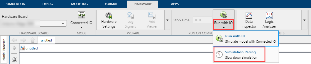
Go to the Hardware tab, and select Run on board > Connected IO (inputs/outputs mode).
Optionally, you can change the rate of simulation by clicking Run with IO. For more information, see Simulation Pacing Options.
Note
The server for Connected IO is built using GNU Tools for ARM Embedded Processors toolchain irrespective of the toolchain configured in model configuration parameters.
Supported STMicroelectronics Boards and Blocks with Connected IO
The Connected IO described here applies to the Embedded Coder® Support Package for STMicroelectronics® STM32 Processors on these STMicroelectronics Processor-Based Boards and STMicroelectronics Discovery™ boards and blocks:
Source blocks: Without Connected IO, these source blocks output zero during simulation. With Connected IO, these blocks read data from the peripherals of the hardware during simulation.
Sink blocks: Without Connected IO, these sink blocks do not have any role during simulation. With Connected IO, these blocks write data to the peripherals of the hardware during simulation.
STMicroelectronics boards Source Blocks Sink Blocks All STMicroelectronics boards
How Connected IO Works
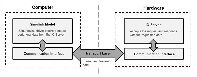
Connected IO creates a communication interface that enables the Simulink model and the IO Server to communicate with each other. The Simulink model resides in your computer, and the IO server is an engine on the hardware that contains all peripheral functions. The transport layer formats and transmits the data using the communication interface.
This diagram shows the connection that the Connected IO creates between your computer and the hardware.
When you simulate a Simulink model with Connected IO:
The device driver blocks (for example, Digital Port Read and Digital Port Write blocks) in the model request peripheral data from the IO Server.
The IO Server accepts the request and responds with the requested data. You can use any Simulink sink or dashboard block to view the received data. Using the peripheral data received, you can verify that your model design meets the requirements.
If necessary, you can modify the design by adding, removing, or replacing any block in the Simulink model.
After the model is modified, resimulate the model. During simulation, the data request from the model is communicated to the hardware. You can continue to modify and simulate the model until the expected behavior is achieved.
Note
The communication in Connected IO is an on-demand process. The hardware sends data only when it receives a data request from the Simulink model.
You do not have to build, deploy, and run the model on the hardware to monitor the effects of your changes in your model design.
Data Acquisition using Connected IO
Data acquisition can be done with connected IO using Polling and Streaming modes.
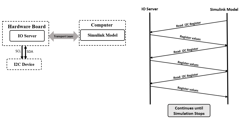
Polling. The communication in polling Connected IO is an on-demand process. The device driver blocks (for example, Digital Port Read, Digital Port Write , Analog to Digital Converter, I2C Controller Read blocks) in the model request peripheral data from the IO Server. The IO Server accepts the request and responds with the requested data. The hardware sends data only when it receives a data request from the Simulink model. In this mode, you can use any number of blocks as required in the model.
Consider the case where data needs to be read from a device connected to the target hardware via I2C, the below diagram shows the interaction between the target and computer in the Polling mode.
Streaming
Streaming mode is used to get higher data acquisition rates for sensor/source blocks. In this mode, the Simulink pre-configures the IO Server on target to process a particular command at the sample rate specified on the block. After the configuration, data is transmitted from the target hardware proactively at the specified rate without additional commands to the target.
Response time for getting data from hardware with streaming is less compared to polling, which allows data acquisitions at high rates.
Streaming requires configuration for each block on the target. Every configuration books memory on the hardware. So, you can use this mode only with a limited number of blocks.
Note
Only the source blocks, for example Digital Port Read, Analog to Digital Converter, can stream data. The sink blocks. for example, Digital Port Write, PWM Output) works in Polling mode.
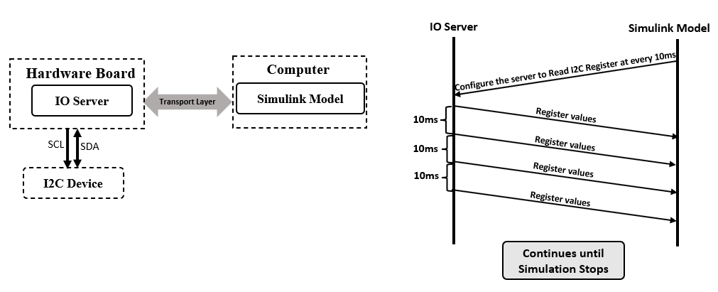
Consider the case where data needs to be read from a device connected to the target hardware via I2C at Sample time 10ms, the below diagram shows the interaction between the target and computer in the Streaming mode.
Note
The communication in Connected IO is an on-demand process when Polling mode is enabled. The hardware sends data only after receiving a data request from the Simulink model.
When Streaming mode is enabled, it helps you to get higher data acquisition rates for source blocks. Simulink pre-configures the IO Server on target to process a particular command at the sample rate specified. The hardware proactively sends data at the specified rate without any additional commands.
You do not have to build, deploy, and run the model on the hardware to monitor the effects of your changes in your model design.
How Connected IO Differs from External Mode
Connected IO and External mode both enable you to communicate with the hardware during simulation. However, you use Connected IO and External mode for different purposes. The table shows the actions that you can perform with each mode.
| Action | External Mode | Connected IO |
|---|---|---|
| Obtain real-time data | You can obtain real-time data with External mode. | Enable simulation pacing to get near real-time data. For more information, see Simulation Pacing Options. |
| Timing analysis of real-time data | Timing analysis of real-time data is possible because the Simulink model is running on the hardware in real-time. | Timing analysis of real-time data is not possible because the Simulink model is running in your computer and not on the hardware. |
| Code generation | Code is generated on the hardware. | No code is generated. |
Connected IO in Model-Based Design
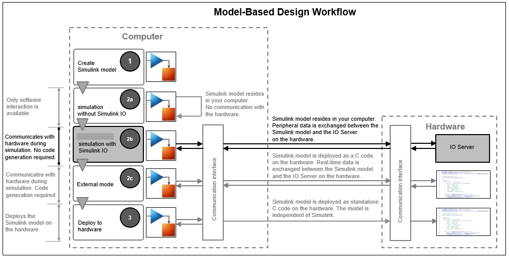
Simulink communicates with the hardware only when the code is generated and the model is deployed on the hardware in External mode. Simulation with Connected IO is an intermediate step in the model-based design workflow that bridges the gap between simulation and code generation by enabling Simulink to communicate with the hardware before you deploy the model on the hardware.
This diagram displays a model-based workflow:
Create a Simulink model.
Simulate the model in one of these modes:
Normal mode simulation without Connected IO: There is no hardware interaction and no code generation.
Simulation with Connected IO: The model communicates with the hardware. There is no code generation.
External mode: The model is deployed on the hardware and generates code.
Deploy the model to the hardware.
Run Simulink Model in Connected IO
Follow these steps to run a Simulink model in connected IO mode:
Open a Simulink model.
On the Modeling tab of the model, select Model Settings.
In the Configuration Parameters dialog box, select Hardware Implementation from the left pane and select the target hardware in the Hardware board parameter.
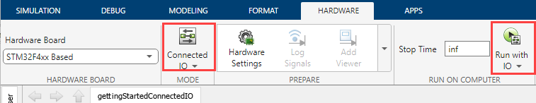
On the Hardware tab of the model, in the Mode section, select
Connected IOand then click Run with IO.
Additionally, you can change the rate of simulation by enabling simulation pacing. For more information, see Simulation Pacing Options.
Connected IO Modes: Auto, Polling, and Streaming
Connected IO provides these modes:
Auto: Auto is the default Connected IO mode. When you select this mode, Simulink automatically chooses the best suitable mode between Polling and Streaming.
If the Simulink model contains only source blocks and if Simulink pacing is enabled with Simulation per wall clock second is set to
1, then Streaming mode is enabled for all source blocks.If the Simulink model contains Sink blocks or if Simulink pacing is disabled, then all the blocks (source and sink blocks) in the model run in Polling mode.
Polling: Polling is the on-demand mode. When you select this mode, both source and sink blocks run in Polling mode.
Select this mode when:
The model has both Source blocks and Sink blocks.
The model has a high number of blocks.
The model has source blocks in event-based subsystems such as Triggered Subsystem, Enabled Subsystem and so on.
The model has applications requiring lock-step operations.
Note
Use polling mode for block characterization (reviewing the properties of the blocks) before you try code generation.
Streaming: Streaming mode supports higher data acquisition rates for sensor/peripheral source blocks. When you select this mode, Source blocks work in Streaming mode and Sink blocks work in Polling mode.
Note
Presence of sink blocks in a model configured for Streaming affects the performance of source blocks.
Select this mode when:
The model has only Source blocks and no Sink blocks.
The model has Sink blocks that requires execution rarely.
Selecting a Connected IO Mode
To simulate a model in Connected IO, select a Connected IO mode using these steps:
Open a Simulink model.
In the Simulink toolbar, set the Simulation mode to
Normal.In the Modeling tab, select Model Settings.
In the Configuration Parameters dialog box, select Hardware Implementation.
Set the Hardware board parameter to a value such as
STM32F4xx Basedboard.The parameter values under Hardware board settings are automatically populated to their default values.
Click Target hardware resources and then click Connected IO.
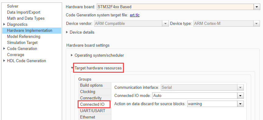
Select the required Connected IO mode from the list.
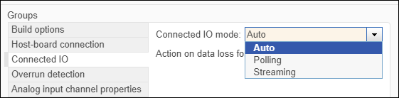
If you select
AutoorStreamingas Connected IO mode, a new parameter Action on data loss or source blocks displays. Data loss while streaming can occur due to following reasons:High sample rate set for the block.
Large number of blocks in the model.
Time consuming operations in the model.
Select the required option.
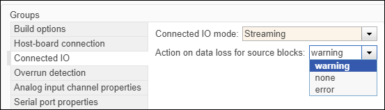
warning:Select this option to display a warning when there is data loss from source blocks while streaming. After simulation, number of data dropped for each block is displayed in the diagnostic viewer.none:Select this option to take no action.error:Select this option to display an error message when there is data loss.
Click Apply and OK.
Streaming Data from Sensors
To read data from sensors, use one of the following options.
Use sensor blocks available in the library, for example ICM20948 IMU Sensor. To stream data from this block, add the block in the model, set the required sample rate, and select the streaming mode as discussed above.
Create a sensor using basic peripheral source blocks (for example,. I2C Register Read, Analog Input). Some sensors require source blocks to implement one-time configurations such as powering on the sensor, setting the range of sensor and so on. These blocks need not stream. In such cases, add such operations or blocks in Initialize Function block. The blocks in the Initialize Subsystem will not be configured for streaming. Only blocks in the main model will be configured for streaming.