ICM20948 IMU Sensor
Measure linear acceleration, angular velocity, magnetic field, and temperature from ICM20948 IMU sensor
Since R2025a
Add-On Required: This feature requires the Embedded Coder Support Package for STMicroelectronics STM32 Processors add-on.
Libraries:
Embedded Coder Support Package for STMicroelectronics STM32 Processors /
Sensors /
IMU Sensors
Description
The ICM20948 IMU Sensor block outputs the values of linear acceleration, angular velocity, and magnetic field strength along x-, y- and z- axes as measured by the ICM20948 IMU sensor connected to an STM32 processor. The block also outputs the temperature read by the ICM20948 IMU sensor.
Examples
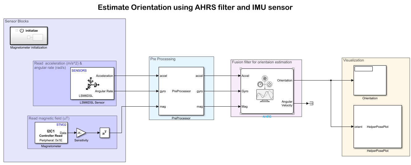
Estimate Orientation Using AHRS Filter and IMU Data on STM32 Processor Based Boards
Stream inertial measurement unit (IMU) data from sensors connected to Nucleo-F302R8 board and estimate its orientation using an attitude and heading reference system (AHRS) filter.
Ports
Output
Parameters
Extended Capabilities
Version History
Introduced in R2025a