Motor Control
Implement open-loop or closed-loop FOC (field-oriented control) techniques for sensor-based and sensorless position applications using PMSM (permanent magnet synchronous motor).
The support package includes reference examples that help you build and deploy motor control applications on STM32 hardware boards (with Motor Control Blockset™ and Embedded Coder®).
Featured Examples

Generate Motor Control Models for Selected Algorithm and Hardware
Use Motor Control Blockset™ to generate a Simulink® model that is configured for a specific hardware and motor control technique.
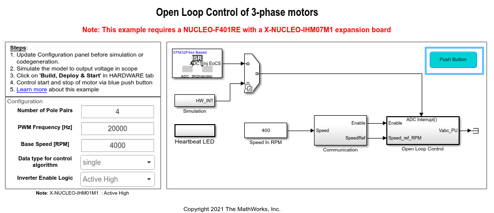
Open-Loop Control of 3-Phase AC Motors Using STM32 Processor Based Boards
Uses open-loop control (also known as scalar control or Volts/Hz control) to run a motor. This technique varies the stator voltage and frequency to control the rotor speed without using any feedback from the motor. You can use this technique to check the integrity of the hardware connections. A constant speed application of open-loop control uses a fixed-frequency motor power supply. An adjustable speed application of open-loop control needs a variable-frequency power supply to control the rotor speed. To ensure a constant stator magnetic flux, keep the supply voltage amplitude proportional to its frequency.

Field-Oriented Control of PMSM Using Position Estimated by Neural Network on STM32 Processor Based Boards
Implement field-oriented control (FOC) of a permanent magnet synchronous motor (PMSM) using rotor position estimated by an auto-regressive neural network (ARNN) trained with Deep Learning Toolbox™.
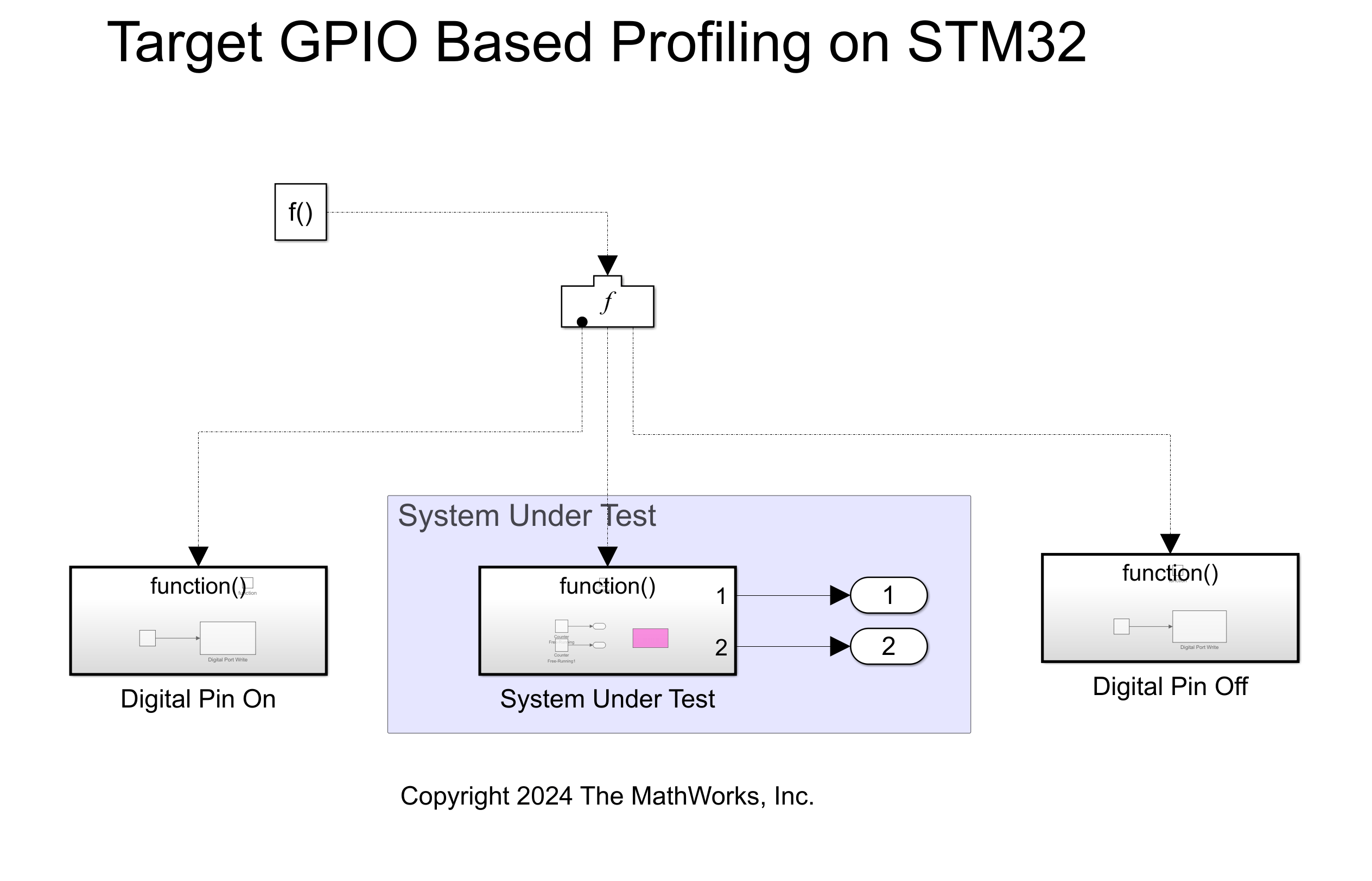
Getting Started with Hardware Profiling
Demonstrates how to perform real-time execution profiling of algorithms using the Embedded Coder® Support Package for STMicroelectronics® STM32 Processors. It covers two primary profiling methods:
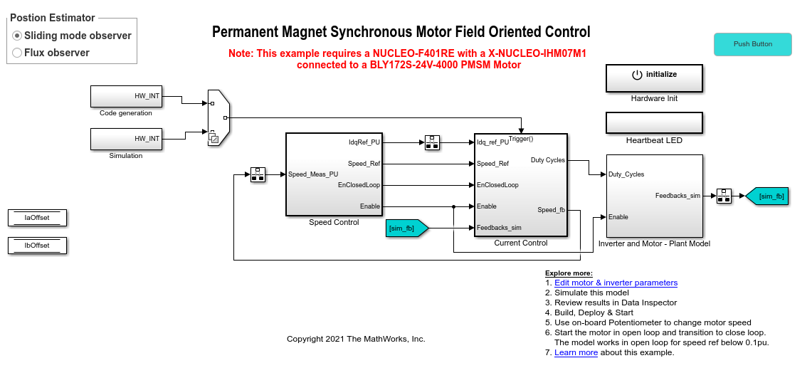
Sensorless Field-Oriented Control of PMSM Using STM32 Processor Based Boards
Implements the field-oriented control (FOC) technique to control the speed of a three-phase permanent magnet synchronous motor (PMSM). For details about FOC, see Field-Oriented Control (FOC) (Motor Control Blockset).
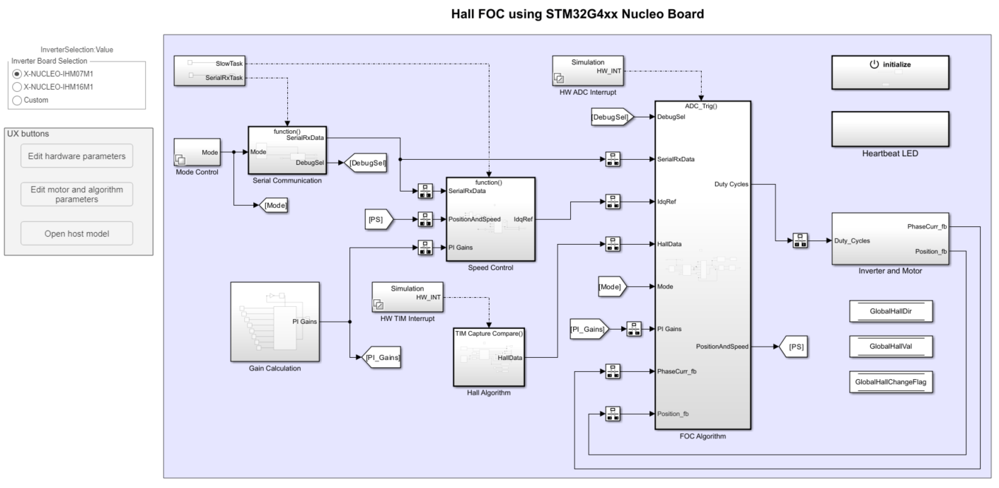
Field-Oriented Control of PMSM with Hall Sensor Using STM32G4xx Based Processors
Implements the field-oriented control (FOC) technique to control the speed of a three-phase permanent magnet synchronous motor (PMSM). The FOC algorithm requires rotor position feedback, which is obtained by a Hall sensor.
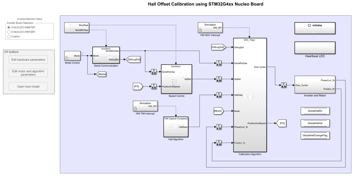
Hall Offset Calibration for PMSM with STM32 Processors
Calculates the offset between the rotor direct axis (d-axis) and position detected by the Hall sensor. The field-oriented control (FOC) algorithm needs this position offset to run the permanent magnet synchronous motor (PMSM) correctly. To compute the offset, the target model runs the motor in the open-loop condition. The model uses a constant (voltage along the stator's d-axis) and a zero (voltage along the stator's q-axis) to run the motor (at a low constant speed) by using a position or ramp generator. When the position or ramp value reaches zero, the corresponding rotor position is the offset value for the Hall sensors.

Estimate PMSM Parameters Using STM32 Processor
Determines the parameters of a permanent magnet synchronous motor (PMSM) using the recommended STM32xx based board. The tool determines these parameters:
Six-Step Commutation of BLDC Motor Using Hall Sensor Feedback for STM32G4xx Based Processors
Control the speed and direction of a three-phase brushless DC (BLDC) motor using the six-step commutation technique in 120-degree conduction mode. The example uses the switching sequence generated by the Six Step Commutation block to control the rotor speed and direction by adjusting the three-phase stator voltages.
Hall Sensor Sequence Calibration for STM32G4xx Based Processors
Control a BLDC motor by calculating the Hall sensor sequence with respect to position zero of the rotor in open-loop control. By using this method, you can use six-step commutation to control the motor without the need to label the Hall sensors or derive the switching sequence. Run this example on STM32G4xx Based Processors and obtain the Hall sequence, and use this Hall sequence with the Six Step Commutation block to run the motor in closed-loop as explained in the Six-Step Commutation of BLDC Motor Using Sensor Feedback for STM32G4xx Based Processors example. The Hall sequence calibration algorithm drives the motor through a full mechanical revolution and computes the Hall sensor sequence relative to the rotor's position zero in open-loop control.