Six-Step Commutation of BLDC Motor Using Hall Sensor Feedback for STM32G4xx Based Processors
This example shows how to control the speed and direction of a three-phase brushless DC (BLDC) motor using the six-step commutation technique in 120-degree conduction mode. The example uses the switching sequence generated by the Six Step Commutation (Motor Control Blockset) block to control the rotor speed and direction by adjusting the three-phase stator voltages.
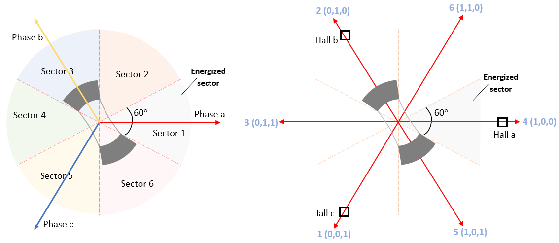
The six-step commutation algorithm requires a Hall sequence or a rotor position feedback value obtained from a Hall sensor. A Hall effect sensor adjusts its output voltage according to the strength of the applied magnetic field. In the standard configuration, a BLDC motor uses three Hall sensors placed 120 electrical degrees apart. These sensors generate six valid binary state combinations: 001, 010, 011, 100, 101, and 110. The sensor outputs the rotor's angular position in 60-degree increments, enabling the controller to identify the 60-degree sector where the rotor is located.
The controller uses the Hall sequence or rotor position to operate the motor. It energizes the next two phases of the stator winding, ensuring the rotor maintains a torque angle of 90 degrees with a permissible deviation of 30 degrees. The Hall sequence may vary. For more information on identifying the correct Hall sequence, see Hall Sensor Sequence Calibration for STM32G4xx Based Processors.
This example supports simulation, allowing you to model a three-phase switching inverter and a wye-wound BLDC motor using components from Simscape™ Electrical™.
Required Hardware
The example supports these hardware configuration. You can also use the target model name to open the model for the corresponding hardware configuration from the MATLAB® command prompt: STM32G431RB Nucleo Board + X-Nucleo-IHM08M1 inverter - stm32_six_step_hall_target

Jumper Name | Description | Status |
|---|---|---|
J1 | DC power supply | |
JP3 | Hall sensor | |
JP1 & JP2 | Closed | |
J5 & J6 | Soldered across the 1Sh pads | |
J9 | Open | |
J16 | Motor phase connections |
Models
The example includes these models:

You can use these models for simulation and code generation.
Prerequisites
1. Obtain motor parameters
Use the default motor parameters provided with the Simulink® model or replace them with values from a motor datasheet or other sources.
To estimate motor parameters for your specific motor, use the parameter estimation tool. The parameter estimation tool updates the
motorParamvariable in the MATLAB® workspace with the estimated parameters. For more information, see Estimate PMSM Parameters Using STM32 Processor.
2. Update model parameters
If you are using motor parameters from a datasheet or other sources, update both the motor and inverter parameters in the model initialization script associated with the Simulink model. For more information, see Estimate Control Gains and Use Utility Functions (Motor Control Blockset).
If you are using the parameter estimation tool, update the inverter parameters only. The script automatically retrieves motor parameters from the
BLDCvariable.
Simulate Model
This example supports simulation. Follow these steps to simulate the model.
1. Open the model included with this example.
2. Click Run on the Simulation tab to simulate the model.
3. Click Data Inspector on the Simulation tab to view and analyze the simulation results.
Generate Code and Deploy Model to Target Hardware
Follow these steps to generate code and deploy the six-step commutation algorithm to your target hardware.
This example uses a host and a target model. The host model is a user interface to the controller hardware board. You can run the host model on the host computer. The prerequisite to use the host model is to deploy the target model to the controller hardware board. The host model uses serial communication to command the target Simulink model and run the motor in a closed-loop control.
1. Simulate the target model and observe the simulation results.
2. Complete the hardware connections.
3. The model computes the ADC (or current) offset values by default. To disable this functionality, update the value 0 to the variable inverter.ADCOffsetCalibEnable in the model initialization script.
Alternatively, you can compute the ADC offset values and update them manually in the model initialization script. For instructions, see Run 3-Phase AC Motors in Open-Loop Control and Calibrate ADC Offset (Motor Control Blockset).
4. If you are using a Hall sensor, compute the Hall sequence value and update it in the bldc.hallsequence variable available in the model initialization script associated with the target model. For instructions, see Hall Sensor Sequence Calibration for STM32G4xx Based Processors.
5. Open the target model. If you want to change the default hardware configuration settings for the model, see Model Configuration Parameters for STM32 Processor Based Boards.
6. Click Build, Deploy & Start on the Hardware tab to deploy the target model to the hardware and load the variables from the target model to the base workspace.
7. Click the host model hyperlink in the target model to open the associated host model.
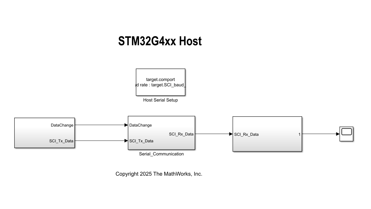
8. In the model initialization script associated with the target model, specify the communication port using the variable target.comport. This variable updates the Port parameter of the Host Serial Setup, Host Serial Receive, and Host Serial Transmit blocks available in the host model.
9. Update the reference speed value in the Reference Speed (RPM) field in the host model.
10. In the host model, select the debug signals that you want to monitor.
11. Click Run on the Simulation tab to run the host model.
12. Change the position of the Motor switch to Start to start running the motor.
13. Observe the debug signals from the RX subsystem, in the Scope and Display blocks in the host model.