EVADC Peripheral Configuration
Map EVADC peripherals in the Infineon AURIX model to peripheral registers in the MCU
Since R2024a
Description
Add-On Required: This feature requires the Embedded Coder Support Package for Infineon AURIX TC3x Microcontrollers add-on.
View and edit the map of peripherals in the Infineon® AURIX™ model to the hardware peripherals.
Using the Peripheral Configuration tool, you can:
View and edit configuration parameters for EVADC peripheral block.
Configure the global parameters. To set the group peripheral, select peripheral in BrowserPeripherals
EVADC. For more information, see Map Tasks and Peripherals Using Hardware Mapping.Check for any conflicts between peripherals.
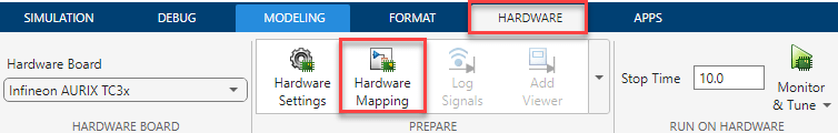
Open the EVADC Peripheral Configuration
In the Hardware tab, click Hardware Mapping.
Parameters
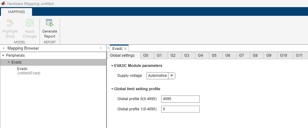
Global parameters > Global settings > EVADC module parameters
Set the voltage supply for EVADC module.
Global parameters > Global settings > Global limit setting profile
Specify the global limit for profile 0.
Specify the global limit for profile 1.
Global parameters > G#
Select to enable group start up calibration.
G# > Request queue #
Select one of these conversion modes:
One-shot— Select this option for a one-time analog-to-digital conversion after a software or hardware trigger event. In case of hardware trigger event, you must add another EVADC block with the block parameter Mode set toADC Triggerto fill the queue input register. You must map these EVADC trigger and read blocks using Select read block parameter in the Group select tab in the Hardware Mapping tool.Refill with trigger— Select this option to wait for either software or hardware trigger for analog-to-digital conversion. This mode automatically refills the queue input register and a valid queue entry waits for a trigger event to initiate conversion.Refill with one time trigger— Select this option for perpetual analog-to-digital conversion of valid queue entries after a software trigger. This mode automatically refills the queue input register.
When you configure PWM block to trigger the analog-to-digital conversion in
One-shot or Refill with
trigger conversion modes, the block converts the channels
sequentially. Each of the EVADC channels requires its own PWM trigger signal to
complete the conversion.
Select queue priority for ADC conversion for group #.
Select slot start mode for ADC conversion for group #.
Select source of gating for ADC conversion request for group #. For more information on EVADC trigger signals, refer to EVADC Trigger Signals.
Select gating mode for ADC conversion request for group #.
Select trigger source for ADC conversion for group #.
Software-Block sample time —Software-Trigger block —GTM ADC trigger signal# —
Select trigger mode for ADC conversion.
Dependencies
To enable this parameter, set the Trigger source
parameter to GTM ADC trigger signal#.
G# > Group limit setting profile
Group limit setting for profile 0.
Group limit setting for profile 1.
Select the controller group to synchronize with G#.
Note
You cannot configure a group as peripheral, if it is already selected as the controller.
You cannot configure a group as the controller, if it is already selected as peripheral.
Group select
Select the EVADC read blocks available in the Simulink® model.
Dependencies
To enable this parameter, set the Mode parameter to
ADC trigger in the EVADC block in the Simulink
model.
Select group for ADC conversion.
Dependencies
To enable this parameter, set the Mode parameter to
ADC read in the EVADC block in the Simulink
model.
Select queue for ADC conversion.
Dependencies
To enable this parameter, set the Mode parameter to
ADC read in the EVADC block in the Simulink
model.
Input #
Select the analog pin for ADC conversion.
Select to use channel 0 input as alternate voltage reference for channels other than channel 0 of the group.
Dependencies
To enable this parameter, set the Select group
parameter to a value other than Channel 0 in the
G# tab.
Select to generate parallel output for same channel numbers of synchronized group.
Dependencies
To enable this parameter, set the Select group parameter to the controller group, which is selected in Synchronize group with parameter in the G# tab.
Input # > Result
Select the result register ranging between Result 0
through Result 15 for EVADC channel group.
Select this parameter to enable the register to wait and read the EVADC channel result registers.
Select to enable left aligned storage of conversion result in result registers.
Specify data modification mode of conversion result in result registers.
Specify data reduction control mode for result register.
Dependencies
To enable this parameter, set the Data modification
modes parameter to Standard Data
Reduction.
Input # > Events
Select criteria for generating limit check interrupts.
Select limit service request node for channel #.
Dependencies
To enable this parameter, select the Limit checking event parameter.
Result event for channel #.
Select result service request node for channel #.
Dependencies
To enable this parameter, select the Result event parameter.
Input # > Limit Checking Configuration
Select boundary extension for channel #.
Dependencies
To enable this parameter, select the Limit checking event parameter.
Select limit check selection for channel #.
Dependencies
To enable this parameter, select the Limit checking event parameter.
Select upper threshold of channel # for checking limit.
Dependencies
To enable this parameter, select the Limit checking event parameter.
Select lower threshold of channel # for checking limit.
Dependencies
To enable this parameter, select the Limit checking event parameter.
Version History
Introduced in R2024a
MATLAB Command
You clicked a link that corresponds to this MATLAB command:
Run the command by entering it in the MATLAB Command Window. Web browsers do not support MATLAB commands.
Select a Web Site
Choose a web site to get translated content where available and see local events and offers. Based on your location, we recommend that you select: .
You can also select a web site from the following list
How to Get Best Site Performance
Select the China site (in Chinese or English) for best site performance. Other MathWorks country sites are not optimized for visits from your location.
Americas
- América Latina (Español)
- Canada (English)
- United States (English)
Europe
- Belgium (English)
- Denmark (English)
- Deutschland (Deutsch)
- España (Español)
- Finland (English)
- France (Français)
- Ireland (English)
- Italia (Italiano)
- Luxembourg (English)
- Netherlands (English)
- Norway (English)
- Österreich (Deutsch)
- Portugal (English)
- Sweden (English)
- Switzerland
- United Kingdom (English)