EVADC
Libraries:
Embedded Coder Support Package for Infineon AURIX TC3x Microcontrollers /
AURIX TC3x
Description
Add-On Required: This feature requires the Embedded Coder Support Package for Infineon AURIX TC3x Microcontrollers add-on.
Measure the voltage of an analog input pin.
The Enhanced Versatile Analog to Digital Converter (EVADC) block outputs the voltage of
the input signal as a 12-bit value in an N-by-1 array, where N is
defined based on the number of channels selected.
Note
If you add the same pin in multiple channels of single EVADC block, then some channels fail to capture the converted result in external mode and Synopsys Virtualizer Studio.
Examples
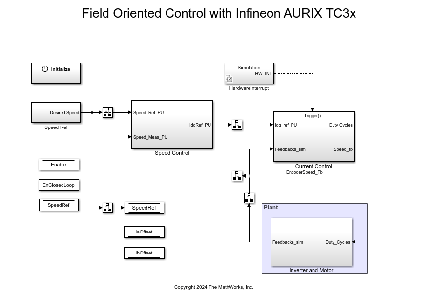
Field-Oriented Control of BLDC with Encoder Using Infineon AURIX TC3xx Microcontrollers
Implement the field-oriented control (FOC) technique to control the speed of a three-phase brushless DC (BLDC) motor. The FOC algorithm requires rotor position feedback, which is obtained by using an encoder sensor. For more details about FOC, see Field-Oriented Control (Motor Control Blockset).
Ports
Input
Output
Parameters
Version History
Introduced in R2024a