Dyadic Analysis Filter Bank
Decompose signals into subbands with smaller bandwidths and slower sample rates or compute discrete wavelet transform (DWT)
Libraries:
DSP System Toolbox /
Filtering /
Multirate Filters
Description
You can configure this block to decompose a broadband signal into a collection of subbands with smaller bandwidths and slower sample rates. The block uses a series of highpass and lowpass FIR filters to repeatedly divide the input frequency range, as illustrated in Multilevel Filter Banks (the Asymmetric one).
You can specify the filter bank highpass and lowpass filters by providing vectors of filter coefficients. You can do so directly on the block mask. If you have a Wavelet Toolbox™ license, you can specify wavelet-based filters by selecting a wavelet from the Filter parameter. You must set the filter bank structure to asymmetric or symmetric, and specify the number of levels in the filter bank.
For the same input, the DWT configuration of this block does not produce the same
results as the Wavelet Toolbox
dwt function. Because DSP System Toolbox™ is designed for real-time implementation and Wavelet Toolbox is designed for analysis, the products handle boundary conditions and
filter states differently. To make the output of the dwt function
match the DWT output of this block, complete the following steps:
Set the boundary condition of the
dwtfunction to zero-padding. To do so, typedwtmode('zpd')at the MATLAB® command line.To match the latency of the block (implemented using FIR filters), add zeros to the input of the
dwtfunction. The number of zeros you add must be equal to the half-length of the filter.
The Dyadic Analysis Filter Bank block is same as the DWT block, but with different default settings.
Examples
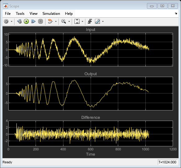
Wavelet Reconstruction and Noise Reduction
Uses the Dyadic Analysis Filter Bank and Dyadic Synthesis Filter Bank blocks to show both the perfect reconstruction property of wavelets and an application for noise reduction.
Ports
Input
Output
The block outputs the dyadic subband decomposition output as a column vector or a matrix. The decomposition output contains elements with the highest-frequency subband first followed by subbands in decreasing frequency.
The output characteristics vary depending on the block parameter settings, as summarized in the following list and figure:
Number of levels parameter set to n
Tree structure parameter setting:
Asymmetric— Block produces n+1 output subbandsSymmetric— Block produces 2n output subbands
Output parameter setting can be
Multiple portsorSingle port. When you set the Output parameter toSingle port, the block outputs one vector or matrix of concatenated subbands. The following figure illustrates the difference between the two settings for a 3-level asymmetric dyadic analysis filter bank. For an explanation of the illustrated output characteristics, see the table Output Characteristics for an n-Level Dyadic Analysis Filter Bank.
For more information about the filter bank levels and structures, see Dyadic Analysis Filter Banks.
Outputs of a 3-Level Asymmetric Dyadic Analysis Filter Bank

The following table summarizes the different output characteristics of the block when you set it to output from single or multiple ports.
Output Characteristics for an n-Level Dyadic Analysis Filter Bank
| Single Output Port | Multiple Output Ports | |
|---|---|---|
| Output Description | Block concatenates all the subbands into one vector or matrix, and outputs the concatenated subbands from a single output port. Each output column contains subbands of the corresponding input channel. | Block outputs each subband from a separate output port. The topmost port outputs the subband with the highest frequencies. Each output column contains a subband for the corresponding input channel. |
| Output Frame Rate | Not applicable | Same as input frame rate |
Output Dimensions (Frame Size) | Same number of rows and columns as the input. | The output has the same number of columns as the input. The number of output rows is the output frame size. For an input with frame size Mi output yk has frame size Mo,k:
|
Output Sample Rate | Same as input sample rate. | Though the outputs have the same frame rate as the input, they have different frame sizes than the input. Thus, the output sample rates Fso,k are different from the input sample rate Fsi:
|
Data Types: single | double
Complex Number Support: Yes
Parameters
Block Characteristics
Data Types |
|
Direct Feedthrough |
|
Multidimensional Signals |
|
Variable-Size Signals |
|
Zero-Crossing Detection |
|
More About
The primary application for dyadic analysis filter banks and dyadic synthesis filter banks is coding for data compression using wavelets.
At the transmitting end, the output of the dyadic analysis filter bank is fed to a lossy compression scheme, which typically assigns the number of bits for each filter bank output in proportion to the relative energy in that frequency band. This represents the more powerful signal components by a greater number of bits than the less powerful signal components.
At the receiving end, the transmission is decoded and fed to a dyadic synthesis filter bank to reconstruct the original signal. The filter coefficients of the complementary analysis and synthesis stages are designed to cancel aliasing introduced by the filtering and resampling.
See Calculate Channel Latencies Required for Wavelet Reconstruction for an example using the Dyadic Analysis and Dyadic Synthesis Filter Bank blocks.
References
[1] Fliege, N. J. Multirate Digital Signal Processing: Multirate Systems, Filter Banks, Wavelets. West Sussex, England: John Wiley & Sons, 1994.
[2] Strang, G. and T. Nguyen. Wavelets and Filter Banks. Wellesley, MA: Wellesley-Cambridge Press, 1996.
[3] Vaidyanathan, P. P. Multirate Systems and Filter Banks. Englewood Cliffs, NJ: Prentice Hall, 1993.
Extended Capabilities
Version History
Introduced before R2006a