designBandpassIIR
Syntax
Description
[
designs a bandpass IIR filter with the filter order of 10, lower 3-dB cutoff frequency
of 0.25, and higher 3-dB cutoff frequency of 0.75. When you use this syntax, the
function designs the IIR filter using the B,A] = designBandpassIIR"default" window design
method and does not compute the scale values.
B and A are the fourth-order section matrices
of the size P-by-5, where P is the number of
filter sections.
The System object™ argument is false by default. To implement the filter,
assign the filter coefficients to a dsp.FourthOrderSectionFilter object.
[
specifies options using one or more name-value arguments.B,A] = designBandpassIIR(Name=Value)
For example, [
designs a bandpass IIR filter with the filter order of 30, lower 3-dB cutoff frequency
of 0.3, and higher 3-dB cutoff frequency of 0.8 by using the Chebyshev Type I window
design method.B,A] =
designBandpassIIR(FilterOrder=30,HalfPowerFrequency1=0.3,HalfPowerFrequency2=0.8,DesignMethod="cheby1",CascadeSectionsForm="sos")
B and A are the second-order section
matrices of the size P-by-3, where P is the number
of filter sections.
When you specify only a partial list of filter parameters, the function designs the filter by setting the other design parameters to their default values.
When you specify any of the numeric input arguments in single precision, the function
designs the filter coefficients in single precision. Alternatively, you can use the Datatype and
like arguments to control the coefficients data
type. (since R2024b)
The function supports three design methods. Each design method supports a specific
set of design combinations. For more information, see DesignMethod.
[
also returns scale values when you specify the B,A,SV] = designBandpassIIR(Name=Value)HasScaleValues
argument. SV is a vector of 1s when you set the argument to
false and a vector of scale values when you set it to
true.
filtObj = designBandpassIIR(Name=Value)dsp.SOSFilter
object or a dsp.FourthOrderSectionFilter object.
This syntax applies when you set the SystemObject argument to
true.
Examples
Create a dsp.FourthOrderSectionFilter object.
fosFilt = dsp.FourthOrderSectionFilter
fosFilt =
  FourthOrderSectionFilter with properties:

      Numerator: [1 0.1000 0.2000 0.3000 0.4000]
    Denominator: [1 0.1000 0.2000 0.3000 0.4000]
Create a spectrumAnalyzer object to visualize the spectra of the input and output signals.
spectrumScope = spectrumAnalyzer(SampleRate=96000,PlotAsTwoSidedSpectrum=false,...
    ChannelNames=["Input Signal","Filtered Signal"]);
Create a dsp.DynamicFilterVisualizer object to visualize the magnitude response of the varying filter.
filterViz = dsp.DynamicFilterVisualizer(NormalizedFrequency=true);
Stream in random data and filter the signal using the dsp.FourthOrderSectionFilter object. Use the designBandpassIIR function to design the filter coefficients. By default, this function returns a P-by-5 matrix of numerator coefficients and a P-by-5 matrix of denominator coefficients. Assign these coefficients to the dsp.FourthOrderSectionFilter object.
Vary the higher 3-dB cutoff frequency of the filter during simulation. The designBandpassIIR function recomputes the coefficients based on the updated filter specifications. Redesign the fourth-order section filter using these updated coefficients. Visualize the spectra of the input and filtered signals using the spectrum analyzer.
F3dB2 = 0.6;
for idx = 1:500
    [b,a] = designBandpassIIR(FilterOrder=30,CascadeSectionsForm="fos",...
        HalfPowerFrequency1=0.25,...
        HalfPowerFrequency2=F3dB2,DesignMethod="cheby1");
    fosFilt.Numerator = b;
    fosFilt.Denominator = a;
    x = randn(1024,1);
    y = fosFilt(x);
    spectrumScope(x,y);
    filterViz(b,a);
    F3dB2 = F3dB2 + 0.0005;
end

Create a dsp.SOSFilter object, and set the CoefficientSource property to 'Input port' so that you can vary the coefficients of the SOS filter through the input port during simulation.
sosFilt = dsp.SOSFilter(CoefficientSource="Input port")sosFilt =
dsp.SOSFilter with properties:
Structure: 'Direct form II transposed'
CoefficientSource: 'Input port'
HasScaleValues: false
Show all properties
Create a spectrumAnalyzer object to visualize the spectra of the input and output signals.
spectrumScope = spectrumAnalyzer(SampleRate=96000,PlotAsTwoSidedSpectrum=false,...
    ChannelNames=["Input Signal","Filtered Signal"]);
Create a dsp.DynamicFilterVisualizer object to visualize the magnitude response of the varying filter.
filterViz = dsp.DynamicFilterVisualizer(NormalizedFrequency=true);
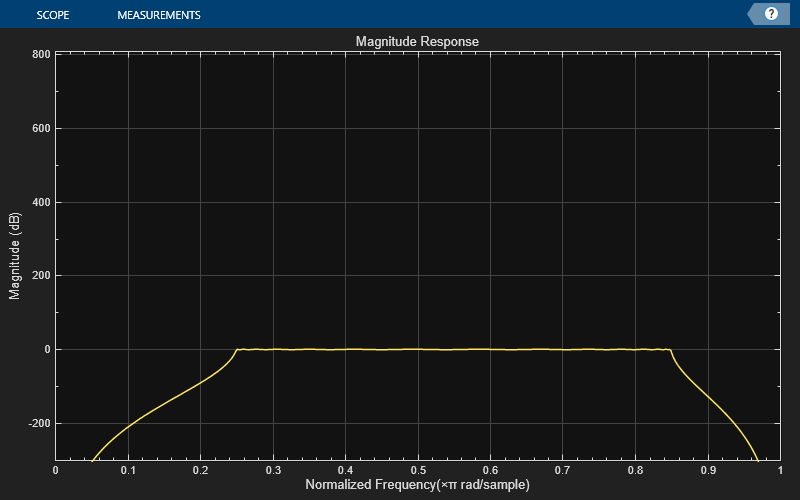
Stream in random data and filter the signal using the dsp.SOSFilter object. Use the designBandpassIIR function to design the filter coefficients. When you set CascadeSectionsForm to "sos", this function returns a P-by-3 matrix of numerator coefficients and a P-by-3 matrix of denominator coefficients. Assign these coefficients to the dsp.SOSFilter object.
Vary the lower 3-dB cutoff frequency of the filter during simulation. The designBandpassIIR function recomputes the coefficients based on the updated filter specifications. Redesign the SOS filter using these updated coefficients. Visualize the spectra of the input and filtered signals using the spectrum analyzer.
F3dB1 = 0.25;
for idx = 1:500
    [b,a] = designBandpassIIR(FilterOrder=30,CascadeSectionsForm="sos",...
        HalfPowerFrequency1=F3dB1,...
        HalfPowerFrequency2=0.75,DesignMethod="butter");
    x = randn(1024,1);
    y = sosFilt(x,b,a);
    spectrumScope(x,y);
    filterViz(b,a);
    F3dB1 = F3dB1 + 0.0005;
end


Design and implement a bandpass IIR filter object using the designBandpassIIR function. The function returns a dsp.FourthOrderSectionFilter object when you set the SystemObject argument to true. To design the filter in single-precision, use the Datatype or like argument. Alternatively, you can specify any of the numerical arguments in single-precision.
fosFilt = designBandpassIIR(FilterOrder=30,DesignMethod="cheby2",...
    Datatype="single",SystemObject=true)
fosFilt =
  FourthOrderSectionFilter with properties:

      Numerator: [8×5 single]
    Denominator: [8×5 single]
Create a dsp.DynamicFilterVisualizer object to visualize the magnitude response of the filter.
filterViz = dsp.DynamicFilterVisualizer(NormalizedFrequency=true,YLimits=[-80 20]);
filterViz(fosFilt)

Create a spectrumAnalyzer object to visualize the spectra of the input and output signals.
spectrumScope = spectrumAnalyzer(SampleRate=44100,PlotAsTwoSidedSpectrum=false,...
    ChannelNames=["Input Signal","Filtered Signal"]);
Stream in random data and filter the signal using the dsp.FourthOrderSectionFilter object. Visualize the spectra of the input and filtered signals using the spectrum analyzer.
for idx = 1:500
    x = randn(1024,1);
    y = fosFilt(x);
    spectrumScope(x,y);
end
