Ideal Ground Truth Sensor
Generate ground truth measurements as sensor detections or track reports from driving scenario or RoadRunner Scenario
Since R2025a
Libraries:
Automated Driving Toolbox /
Driving Scenario and Sensor Modeling
Description
The Ideal Ground Truth Sensor block generates detection or track reports for ground truth measurements of target actors in field of view. It also generates ground truth lane boundaries as lane detections. Use this block to generate ground truth data as sensor detections from a driving scenario containing actors and trajectories, which you can read from a Scenario Reader block. When used in a driving scenario, the block generates detections only for vehicle actors in the scenario.
You can use the block with vehicle actors in RoadRunner Scenario simulations. When used in a RoadRunner Scenario, simulation, the block generates ground truth detections for vehicle actors as well as other static actors such as buildings, traffic cones etc. For more information, see Add Sensors to RoadRunner Scenario Using Simulink example.
Examples
Add Sensors to RoadRunner Scenario Using Simulink
Simulate a RoadRunner Scenario with sensor models defined in Simulink® and visualize object and lane detections.
Ports
Output
Object detections, returned as a Simulink bus containing a MATLAB structure. For more details about buses, see Create Nonvirtual Buses (Simulink).
The detections structure has this form:
| Field | Description | Type |
|---|---|---|
NumDetections | Number of detections | Integer |
IsValidTime | False when updates are requested at times that are between block invocation intervals | Boolean |
Detections | Object detections | Array of object detection structures of length set by the
Maximum number of object detections reported parameter.
Only NumDetections of these detections are actual
detections. |
The object detection structure contains these properties.
| Property | Definition |
|---|---|
Time | Measurement time |
Measurement | Object measurements |
MeasurementNoise | Measurement noise covariance matrix |
SensorIndex | Unique ID of the sensor |
ObjectClassID | Object classification |
MeasurementParameters | Parameters used by initialization functions of nonlinear Kalman tracking filters |
ObjectAttributes | Additional information passed to tracker |
The Measurement field reports the position and velocity of a
measurement in the coordinate system specified by Coordinate system used to
report objects. This field is a real-valued column vector of the form
[x; y; z;
vx; vy; vz]. Units are in
meters per second.
The MeasurementNoise field is a 6-by-6 matrix that reports the
measurement noise covariance for each coordinate in the Measurement
field.
The MeasurementParameters field is a structure with these
fields.
| Parameter | Definition |
|---|---|
Frame | Enumerated type indicating the frame used to report measurements. The
Ideal Ground Truth Sensor block reports detections in
either ego and sensor Cartesian coordinates, which are both rectangular
coordinate frames. Therefore, for this block, Frame is
always set to 'rectangular'. |
OriginPosition | 3-D vector offset of the sensor origin from the ego vehicle origin. The vector is derived from the Sensor's (x,y,z) position (m) parameter of the block. |
Orientation | Orientation of the sensor coordinate system with respect to the ego vehicle coordinate system. The orientation is derived from the Yaw angle of sensor mounted on ego vehicle (deg), Pitch angle of sensor mounted on ego vehicle (deg), and Roll angle of sensor mounted on ego vehicle (deg) parameters of the block. |
HasVelocity | Indicates whether measurements contain velocity. |
The ObjectAttributes property of each detection is a
structure with these fields.
| Field | Definition |
|---|---|
TargetIndex | Identifier of the actor, ActorID, that generated the
detection. For false alarms, this value is negative. |
Dependencies
To enable this output port, set these options:
Types of detections generated by sensor parameter must be
Objects onlyorObjects and LanesOutput format of reported targets must be
Object Detections.
Object tracks, returned as a Simulink bus containing a MATLAB structure. See Create Nonvirtual Buses (Simulink).
This table shows the structure fields.
| Field | Description |
|---|---|
NumTracks | Number of tracks |
Tracks | Array of track structures of a length set by the Maximum number
of tracks parameter. Only the first
NumTracks of these are actual tracks. |
This table shows the fields of each track structure.
| Field | Definition |
|---|---|
TrackID | Unique track identifier used to distinguish multiple tracks. |
BranchID | Unique track branch identifier used to distinguish multiple track branches. |
SourceIndex | Unique source index used to distinguish tracking sources in a multiple tracker environment. |
UpdateTime | Time at which the track is updated. Units are in seconds. |
Age | Number of times the track was updated. |
State | Value of state vector at the update time. |
StateCovariance | Uncertainty covariance matrix. |
ObjectClassID | Integer value representing the object classification. The value
0 represents an unknown classification. Nonzero
classifications apply only to confirmed tracks. |
TrackLogic | Confirmation and deletion logic type. This value is always
'History' for radar sensors, to indicate
history-based logic. |
TrackLogicState | Current state of the track logic type, returned as a 1-by-K logical array. K is the number of latest track logical states recorded.
In the array, |
IsConfirmed | Confirmation status. This field is true if the track
is confirmed to be a real target. |
IsCoasted | Coasting status. This field is true if the track is
updated without a new detection. |
IsSelfReported | Indicate if the track is reported by the tracker. This field is
used in a track fusion environment. It is returned as
|
ObjectAttributes | Additional information about the track. |
For more details about these fields, see objectTrack.
The block outputs one track per target actor.
Dependencies
To enable this port, on the Parameters tab, set the
Output format of reported targets parameter to
Tracks.
Target poses, returned as a Simulink bus containing a MATLAB structure.
A target pose defines the position, velocity, and orientation of a target in ego vehicle coordinates. Target poses also include the rates of change in actor position and orientation.
The structure has these fields:
| Field | Description |
|---|---|
ActorID | Scenario-defined actor identifier, specified as a positive integer. |
ClassID | Classification identifier, specified as a nonnegative integer. 0
represents an object of an unknown or unassigned class. |
Position | Position of actor, specified as a real-valued vector of the form [x y z]. Units are in meters. |
Velocity | Velocity (v) of actor in the x-, y-, and z-directions, specified as a real-valued vector of the form [vx vy vz]. Units are in meters per second. |
Roll | Roll angle of actor, specified as a real scalar. Units are in degrees. |
Pitch | Pitch angle of actor, specified as a real scalar. Units are in degrees. |
Yaw | Yaw angle of actor, specified as a real scalar. Units are in degrees. |
AngularVelocity | Angular velocity (ω) of actor in the x-, y-, and z-directions, specified as a real-valued vector of the form [ωx ωy ωz]. Units are in degrees per second. |
Dependencies
To enable this port, on the Parameters tab, set the
Output format of reported targets parameter to
Target Poses.
Lane boundary detections, returned as a Simulink bus containing a MATLAB structure. The structure has these fields:
| Field | Description |
| Lane boundary coordinates, returned as a real-valued N-by-3 matrix, where N is the number of lane boundary coordinates. Lane boundary coordinates define the position of points on the boundary at returned longitudinal distances away from the ego vehicle, along the center of the road. This matrix also includes the boundary coordinates at zero distance from the ego vehicle. These coordinates are to the left and right of the ego vehicle origin, which is located under the center of the rear axle. Units are in meters. |
| Lane boundary curvature at each row of the
Coordinates matrix, returned as a real-valued
N-by-1 vector. N is the number of
lane boundary coordinates. Units are in radians per meter. |
| Derivative of lane boundary curvature at each row of the
Coordinates matrix, returned as a real-valued
N-by-1 vector. N is the number of
lane boundary coordinates. Units are in radians per square meter. |
| Initial lane boundary heading angle, returned as a real scalar. The heading angle of the lane boundary is relative to the ego vehicle heading. Units are in degrees. |
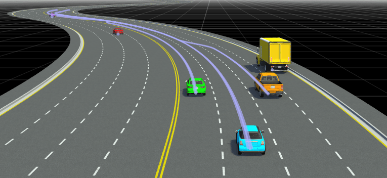
| Lateral offset of the ego vehicle position from the lane boundary, returned as a real scalar. An offset to a lane boundary to the left of the ego vehicle is positive. An offset to the right of the ego vehicle is negative. Units are in meters. In this image, the ego vehicle is offset 1.5 meters from the left lane and 2.1 meters from the right lane.
|
| Type of lane boundary marking, returned as one of these values:
|
| Saturation strength of the lane boundary marking, returned as a
real scalar from 0 to 1. A value of |
| Lane boundary width, returned as a positive real scalar. In a double-line lane marker, the same width is used for both lines and for the space between lines. Units are in meters. |
| Length of dash in dashed lines, returned as a positive real scalar. In a double-line lane marker, the same length is used for both lines. |
| Length of space between dashes in dashed lines, returned as a positive real scalar. In a dashed double-line lane marker, the same space is used for both lines. |

Dependencies
To enable this output port, set the Types of detections generated by
sensor parameter to Objects and
Lanes.
Parameters
Extended Capabilities
Version History
Introduced in R2025a