Passive Control of Water Tank Level
In this example, you learn how to use Control System Tuner app to design a controller for a nonlinear plant modeled in Simulink®. You accomplish the following tasks:
Configure the model and app for compensator tuning
Tune a first-order compensator using passivity-based design
Simulate the closed-loop nonlinear response.
Simulink Model of the Control System
The cst_watertank_comp_design model, models a feedback loop for regulating the water level in a water tank. The Controller block contains the first-order compensator to be tuned.
mdl = 'cst_watertank_comp_design';
open_system(mdl)

The Water Tank subsystem models the water-tank dynamics. Water enters the tank from the top at a rate proportional to the voltage, V, applied to the pump. The water leaves through an opening in the tank base at a rate that is proportional to the square root of the water height, H, in the tank. The presence of the square root in the water flow rate makes the plant nonlinear.
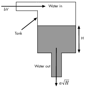
The nonlinear model for the water flow is


where
 denotes the height of water in the tank
 denotes the voltage applied to the pump
 denotes the cross-sectional area of the tank
 and
and  are constants related to the flow rate into and out of the tank
This system is passive with storage function  since
since

Passivity-Based Control
By the Passivity Theorem, the negative-feedback interconnection of two strictly passive systems  and
and  is always stable.

Since the water tank system is passive, it makes sense to require that the controller be strictly passive to guarantee closed-loop stability even when the plant model is inaccurate.
Compensator Tuning Using Control System Tuner
You can use the Control System Tuner app to tune the Controller block.
Step 1: Open the Control System Tuner app. In the Simulink model window, on the Apps tab, in the Apps gallery, click Control System Tuner.
Step 2: Launch the tuned block selector from the Select Blocks button in the Tuning tab.

Step 3: Select the Controller block and Click OK. This block now appears in the Tuned Blocks list.

Step 4: Specify the tuning goals. Here, there are two main goals:
Track step changes in water level
Make the controller passive
Click the New Goal drop-down list, and first add a Passivity goal.
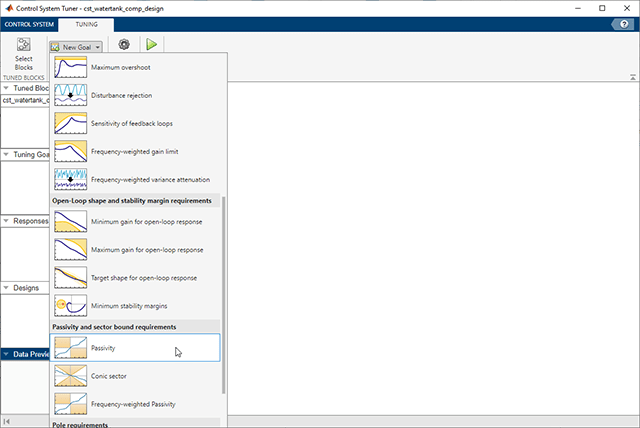
Configure this goal to apply to the Controller block only. This is done by setting the input signal to be the "Desired Water Level", the output signal to be the output of the Controller block, and the loop opening to be at the Controller block output. Also specify minimum passivity indices of 0.01 at the inputs and outputs to enforce strict passivity.

Next, add a Reference Tracking goal from the New Goal drop-down list. Configure this goal for a 1 second response time.

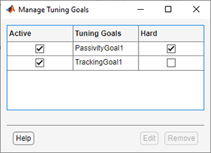
Finally, click the Manage Goals button off the Tuning tab and mark the Passivity goal as a hard tuning constraint.
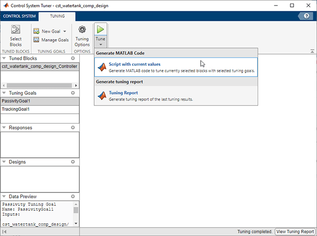
Step 5: You are ready to tune the Controller block. Click the Tune button. You can view the tuning results side-by-side by selecting Left/Right in the View tab.
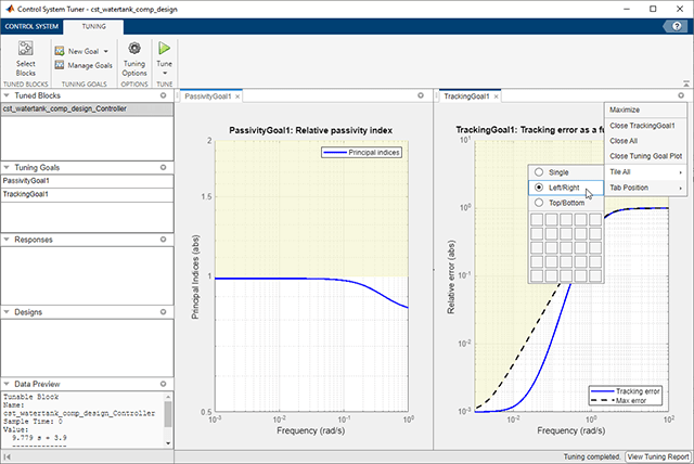
You can further analyze these results by generating a MATLAB® script that reproduces this tuning process.
Closed-Loop Simulation
You can view the Bode plot of the tuned controller. Click the New Plot button off the Control System tab. Select New Bode from the drop-down list.

The controller response can be specified as follows.
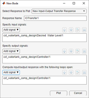
Click the Plot button. The bode plot is shown in the following figure.

You can also simulate the closed-loop nonlinear response with the tuned controller. First, update the Controller block by clicking Update Blocks in the Control System tab.

In the Simulink model, double click the Scope block to open the Scope window, then simulate the model.
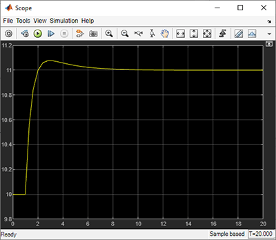
The nonlinear response of the tuned control system appears in the Scope window. This simulation shows that the tracking performance is satisfactory.