comm.RayTracingChannel
Filter signal through multipath fading channel defined by propagation rays
Description
The comm.RayTracingChannel
System object™ filters a signal through a multipath fading channel that is defined by
propagation rays. For more information, see the Channel Impulse Response section.
To filter an input signal through a fading channel defined by propagation rays:
Create the
comm.RayTracingChannelobject and set its properties.Call the object with arguments, as if it were a function.
To learn more about how System objects work, see What Are System Objects?
Creation
Syntax
Description
rtchan = comm.RayTracingChannel
rtchan = comm.RayTracingChannel(Name=Value)comm.RayTracingChannel(SampleRate=1e6) sets the sample rate to 1
MHz.
rtchan = comm.RayTracingChannel(rays,tx,rx)rays, tx, and
rx. Use this syntax when the rays input
argument is a comm.Ray object created using the
raytrace function.
The
raysinput argument is a set ofcomm.Rayobjects that specify the propagation path. The channel uses theraysinput to set thePropagationRaysproperty.The
txinput argument is atxsiteobject and sets theTransmitArrayandTransmitArrayOrientationAxesproperties. Use the sametxobject that created thecomm.Rayobject to keep the channel configuration consistent with the original scenario.The
rxinput argument is anrxsiteobject and sets theReceiveArrayandReceiveArrayOrientationAxesproperties. Use the samerxobject that created thecomm.Rayobject to keep the channel configuration consistent with the original scenario.
When you use this syntax to configure other properties, set their values after creating the System object. For an example, see Configure Sample Rate for Ray Tracing Channel.
Properties
Usage
Syntax
Description
cir = rtchan()ChannelFiltering property to false.
cir = rtchan(starttime)ChannelFiltering property to false.
Input Arguments
Output Arguments
Object Functions
To use an object function, specify the
System object as the first input argument. For
example, to release system resources of a System object named obj, use
this syntax:
release(obj)
Examples
Show the impact of not forcing the smallest propagation delay to be zero for a multipath channel model. Filter signals through a multipath ray tracing channel between two sites in Hong Kong, China. Build two multipath channel models by using the result from ray tracing. For the first ray tracing channel model, force the minimum propagation delay to zero. For the second ray tracing channel model, do not force the minimum propagation delay to zero.
Create a Site Viewer map display of buildings in Hong Kong. For more information about the OSM file, see [1].
sv = siteviewer("Buildings","hongkong.osm");

tx = txsite( ...
    "Latitude",22.2789, ...
    "Longitude",114.1625, ...
    "AntennaAngle",30, ...        % Azimuth angle
    "AntennaHeight",10, ...
    "TransmitterFrequency",28e9);
rx = rxsite( ...
    "Latitude",22.2799, ...
    "Longitude",114.1617, ...
    "AntennaAngle",120, ...       % Azimuth angle
    "AntennaHeight",1);
Create a ray tracing propagation model, which MATLAB® represents using a RayTracing object. Configure the model to use the image method and to find paths with up to 2 surface reflections. Perform ray tracing to find rays by using the propagation model.
pm = propagationModel("raytracing", ...
    "Method","image", ...
    "MaxNumReflections",2);
rays = raytrace(tx,rx,pm);
Create a channel model using the calculated rays in between the transmitter and receiver sites. The default configuration forces zero minimum propagation delay. Show the temporal and spatial profiles of the channel.
rtchan = comm.RayTracingChannel(rays{1},tx,rx);
rtchan.SampleRate = 50e6;
showProfile(rtchan);
Create a clone of the ray tracing channel model and reconfigure it to not force zero minimum propagation delay. Show the temporal and spatial profiles of the channel. The angle of departure and arrival plots do not change, but the power delay profile plot shows the updated delay profile result when the minimum delay profile is not forced to zero.
rtchandelayed= clone(rtchan);
rtchandelayed.MinimizePropagationDelay = false;
showProfile(rtchandelayed);

Filter randomly generated 16-QAM signals through the channel models. Display the leading 15 elements of y and ydelayed, which are output by the ray tracing channel objects rtchan and rtchandelayed, respectively. The leading samples in the delayed signal, ydelayed, are all zeros. When you model your communications system, you must account for this signal delay to avoid losing trailing signal data.
M = 16;       % Modulation order
frmLen = 1e3; % Frame length
numTx = rtchan.info.NumTransmitElements;

x = qammod(randi([0,M-1],frmLen,numTx),M);
y = rtchan(x);
numTxdelayed = rtchandelayed.info.NumTransmitElements;
x = qammod(randi([0,M-1],frmLen,numTxdelayed),M);
ydelayed = rtchandelayed(x);
y(1:15)
ydelayed(1:15)
ans = 15×1

    0
    0
    0
    0
    0
    0
    0
    0
    0
    0
      ⋮
Appendix
[1] The OSM file is downloaded from https://www.openstreetmap.org, which provides access to crowd-sourced map data all over the world. The data is licensed under the Open Data Commons Open Database License (ODbL), https://opendatacommons.org/licenses/odbl/.
Filter signals through a multipath ray tracing channel model between two sites in a conference room. Build the multipath channel model by using the result from ray tracing.
Define a 3-D map for a conference room with one table and four chairs by using a standard tessellation language (STL) data file. Define a transmitter site close to the wall and a receiver site above the table.
mapFileName = "conferenceroom.stl";

tx = txsite("cartesian", ...
    "AntennaPosition",[-1.45; -1.4; 2.3], ...
    "TransmitterFrequency",2.8e9);
rx = rxsite("cartesian", ...
    "AntennaPosition",[.6; .2; 1.0]);
Use the siteviewer object and the show object function to visualize the 3-D scenario. The transmitter and receiver sites are colored in red and blue, respectively.
siteviewer(SceneModel=mapFileName);
show(tx,"ShowAntennaHeight",false)
show(rx,"ShowAntennaHeight",false)
Create a ray tracing propagation model, which MATLAB represents using a RayTracing object. Configure the model to find paths with up to 3 surface reflections. By default, the model uses the shooting and bouncing rays (SBR) method.
pm = propagationModel("raytracing", ...
    "CoordinateSystem","cartesian", ...
    "MaxNumReflections",3);
Perform ray tracing to find rays by using the propagation model.
rays = raytrace(tx,rx,pm,"Map",mapFileName);Extract the computed rays from the returned cell array, and then plot the rays. Each ray is colored based on its path loss value.
rays = rays{1,1};
plot(rays)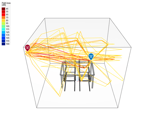
Create a channel model using the calculated rays in between the transmitter and receiver sites. Show the temporal and spatial profiles of the channel.
rtchan = comm.RayTracingChannel(rays,tx,rx);
showProfile(rtchan);

Show the filtered signal in a constellation diagram.
M = 16;       % Modulation order
frmLen = 1e3; % Frame length

numTx = rtchan.info.NumTransmitElements;
x = qammod(randi([0,M-1],frmLen,numTx),M);
rtchan.SampleRate = 10e6
rtchan =
  comm.RayTracingChannel with properties:

                      SampleRate: 10000000
                 PropagationRays: [1×50 comm.Ray]
        MinimizePropagationDelay: true
                   TransmitArray: [1×1 arrayConfig]
    TransmitArrayOrientationAxes: [3×3 double]
                    ReceiveArray: [1×1 arrayConfig]
     ReceiveArrayOrientationAxes: [3×3 double]
         ReceiverVirtualVelocity: [3×1 double]
       NormalizeImpulseResponses: true
         NormalizeChannelOutputs: true
                ChannelFiltering: true
y_samprate10e6 = rtchan(x);
constellationdiag = comm.ConstellationDiagram( ...
   NumInputPorts=1, ...
  ChannelNames={"Frequency response channel"}, ...
    XLimits=[-5 5], ...
    YLimits=[-5 5], ...
    ReferenceConstellation=qammod(0:M-1,M));
constellationdiag(y_samprate10e6(:));

At 10e6 sample rate, the diagram shows well-defined and tightly clustered points around the ideal 16-QAM constellation positions. This indicates that the channel has not significantly altered the signal and that the channel introduces minimal ISI and distortion. In a conference room where the primary focus is on maintaining a stable and predictable channel behavior this delay profile is ideal.
For the selected sample rate (10e6), the delay spread of the multiple rays is too low. A higher sample rate would capture the temporal variations and also introduce significant ISI and distortion.
To modify the sample rate of the ray tracing channel, you can set the SampleRate property by using a name-value argument when you create the object or you can create a channel model by using the rays and site and set the SampleRate property after you create the object.
Set Sample Rate when Creating Ray Tracing Channel Object
Create a ray tracing channel model, specifying the sample rate as 20 MHz.
rtchan1 = comm.RayTracingChannel(SampleRate=2e7)
rtchan1 =
  comm.RayTracingChannel with properties:

                      SampleRate: 20000000
                 PropagationRays: [1×1 comm.Ray]
        MinimizePropagationDelay: true
                   TransmitArray: [1×1 arrayConfig]
    TransmitArrayOrientationAxes: [3×3 double]
                    ReceiveArray: [1×1 arrayConfig]
     ReceiveArrayOrientationAxes: [3×3 double]
         ReceiverVirtualVelocity: [3×1 double]
       NormalizeImpulseResponses: true
         NormalizeChannelOutputs: true
                ChannelFiltering: true
Set Sample Rate After Creating Ray Tracing Channel Object
Create a channel model by using the transmitter site, receiver site, and calculated rays between the sites. After creating the object, set the sample rate to 20 MHz.
tx = txsite( ...
    Latitude=22.2789, ...
    Longitude=114.1625, ...
    AntennaAngle=30, ...        % Azimuth angle
    AntennaHeight=10, ...
    TransmitterFrequency=28e9);
rx = rxsite( ...
    Latitude=22.2799, ...
    Longitude=114.1617, ...
    AntennaAngle=120, ...       % Azimuth angle
    AntennaHeight=1);
pm = propagationModel("raytracing", ...
    Method="sbr", ...
    MaxNumReflections=3);
rays = raytrace(tx,rx,pm);

rtchan2 = comm.RayTracingChannel(rays{1},tx,rx);
rtchan2.SampleRate = 2e7
rtchan2 =
  comm.RayTracingChannel with properties:

                      SampleRate: 20000000
                 PropagationRays: [1×2 comm.Ray]
        MinimizePropagationDelay: true
                   TransmitArray: [1×1 arrayConfig]
    TransmitArrayOrientationAxes: [3×3 double]
                    ReceiveArray: [1×1 arrayConfig]
     ReceiveArrayOrientationAxes: [3×3 double]
         ReceiverVirtualVelocity: [3×1 double]
       NormalizeImpulseResponses: true
         NormalizeChannelOutputs: true
                ChannelFiltering: true
After configuring the channel object, you would typically filter a modulated signal through the channel. Here a 16-QAM signal is passed through the rtchan2 ray tracing channel.
modOrd = 16;
frmLen = 1e3;
numTx = rtchan2.info.NumTransmitElements;
x = qammod(randi([0,modOrd-1],frmLen,numTx),modOrd);
y = rtchan2(x);
This example shows how antenna polarization alignment affects signal transmission in a ray tracing channel. It compares two scenarios, one with matched polarization and one with mismatched polarization, and demonstrates the impact on received signal strength.
Set up the carrier frequency and input signal.
fc = 3.5e9;  % 3.5 GHz
Nf = 10;     % Frame size
rng("default")
x = randn(Nf,1,like=1i);  % Complex baseband input signal
For scenario 1, configure polarization-matched antennas.
txElem1 = phased.NRAntennaElement(PolarizationAngle=0);  % Vertical
rxElem1 = phased.NRAntennaElement(PolarizationAngle=0);  % Vertical
Use the polarization-matched antennas in a transmitter and receiver site.
tx1 = txsite("cartesian", Antenna=txElem1, AntennaPosition=[0; 0; 0], TransmitterFrequency = fc);
rx1 = rxsite("cartesian", Antenna=rxElem1, AntennaPosition=[10; 0; 0]);  % 10 meters away
Create a line-of-sight (LOS) ray tracing model and channel.
pm1 = propagationModel("raytracing", CoordinateSystem="cartesian", Method="sbr", MaxNumReflections=0);
rays1 = raytrace(tx1, rx1, pm1);
rays1 = rays1{1,1};
chan1 = comm.RayTracingChannel(rays1, tx1, rx1);
y1 = chan1(x);
For scenario 2, configure polarization-mismatched antennas.
txElem2 = phased.NRAntennaElement(PolarizationAngle=0);   % Vertical
rxElem2 = phased.NRAntennaElement(PolarizationAngle=90);  % Horizontal
Use the polarization-mismatched antennas in a transmitter and receiver site.
tx2 = txsite("cartesian", Antenna=txElem2, AntennaPosition=[0; 0; 0], TransmitterFrequency=fc);
rx2 = rxsite("cartesian", Antenna=rxElem2, AntennaPosition=[10; 0; 0]);
Create a LOS ray tracing model and channel.
rays2 = raytrace(tx2, rx2, pm1);
rays2 = rays2{1,1};
chan2 = comm.RayTracingChannel(rays2, tx2, rx2);
y2 = chan2(x);
Compare the received signal strength for both scenarios.
Display the absolute value of polarization-matched output magnitude.
disp(abs(y1))
    1.3513
    1.7096
    0.9518
    0.3908
    3.1996
    2.3487
    0.5149
    0.5258
    1.0570
    1.4131
Display the absolute magnitude of polarization-mismatched output magnitude.
disp(abs(y2))
     0
     0
     0
     0
     0
     0
     0
     0
     0
     0
The result shows that polarization mismatch can cause severe signal attenuation. When the transmitter and receiver antennas are aligned (vertical, vertical), the signal is received with expected path loss. When they are orthogonal (vertical, horizontal), the signal is nearly eliminated due to polarization loss. This comparison highlights the importance of polarization alignment in wireless system design.
More About
Tips
When you set the
MinimizePropagationDelayproperty totrue, the System object shifts all propagation delay paths to remove the amount of delay that is associated with the minimum propagation delay path. Shifting the paths removes potential leading zeros in the channel output and eliminates the need to account for the delay to receive the trailing signal samples.
Extended Capabilities
Version History
Introduced in R2020bSee Also
Objects
arrayConfig|siteviewer|rxsite|txsite|comm.Ray|comm.ChannelFilter|phased.IsotropicAntennaElement(Phased Array System Toolbox) |phased.ULA(Phased Array System Toolbox) |phased.URA(Phased Array System Toolbox) |phased.ConformalArray(Phased Array System Toolbox) |phased.CustomAntennaElement(Phased Array System Toolbox) |phased.NRAntennaElement(Phased Array System Toolbox) |phased.NRRectangularPanelArray(Phased Array System Toolbox)