Configure Elements of AUTOSAR Software Component for Simulink Modeling Environment
After you create a representation of the AUTOSAR software component in the Simulink® Editor, configure elements of the software component for use in Simulink. The configuration maps AUTOSAR software component elements to Simulink modeling elements.
AUTOSAR Blockset software reduces the effort of setting up a configuration by providing an AUTOSAR Component Quick Start tool. If necessary, you can modify the initial configuration by using the Code Mappings editor and the AUTOSAR Dictionary.
Set Up Initial Component Configuration
Set up an initial configuration of an AUTOSAR software component by using the AUTOSAR Component Quick Start tool.
To open example model
swcthat is not configured for the AUTOSAR platform enter this command in your MATLAB® Command Window:openExample("autosarblockset/GettingStartedWithAUTOSARCodeGenerationExample","supportingFile","swc");
Save a copy of the example model to a writable folder on your current MATLAB search path. Name the file
my_autosar_swc.slx.Set model configuration parameter System target file to
autosar.tlc.Run the AUTOSAR Component Quick Start tool. From the Apps tab, open the AUTOSAR Component Designer app. When you open the app for an unmapped model that is configured with an AUTOSAR system target file, the AUTOSAR Component Quick Start tool runs.
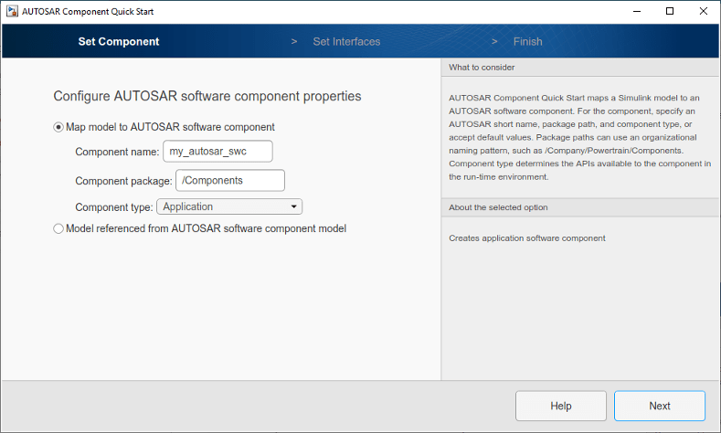
Advance through the steps of the AUTOSAR Component Quick Start tool. Each step prompts you for input that the tool uses to configure your AUTOSAR software component for the Simulink environment.
The name, package, and type of the AUTOSAR software component that you are configuring.
Whether you want to use default properties based on the model or import AUTOSAR software component properties from an ARXML file.
For this tutorial, use the defaults.
After you click Finish, the tool:
Creates a mapping between elements of the AUTOSAR software component and Simulink model elements.
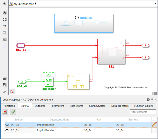
Opens the model in the Simulink Editor AUTOSAR Code perspective. The AUTOSAR Code perspective displays the model and directly below the model, the Code Mappings editor.
Displays the AUTOSAR software component mappings in the Code Mappings editor, which you can use to customize the configuration.
Save the model.
Customize Component Configuration
The AUTOSAR Component Quick Start tool sets up an initial configuration for an AUTOSAR software component. To refine or make changes to an existing component configuration, use the Code Mappings editor and the AUTOSAR Dictionary.
In a tabbed table format, the Code Mappings editor displays Simulink model elements, such as entry-point functions, inports, outports, and data transfers. Use the editor to map Simulink model elements to AUTOSAR software component elements. AUTOSAR software component elements are defined in the AUTOSAR standard. They include runnable entities, ports, and inter-runnable variables (IRVs).
If not already open, open model
my_autosar_swc.In the Code Mappings editor, select the Inports tab.
Select model inport
In1_1s. Selecting the inport highlights the corresponding element in the model. The inport is mapped to AUTOSAR portIn1_1sand data elementIn1_1swith data access modeImplicitReceive.In each Code Mappings editor tab, you can select model elements and modify their AUTOSAR mapping and attributes. Modifications are reflected in generated ARXML descriptions and C code.
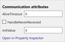
Modify additional mapping properties by using the attribute settings for a mapped model element. For this tutorial, modify communication attributes for inport
In1_1s. Click the icon and:
Set AliveTimeout to 30
Select HandleNeverReceived
Set InitValue to 1
Save the model.
Configure AUTOSAR Software Component Elements from AUTOSAR Standard Perspective
Configure AUTOSAR software component elements from the perspective of the AUTOSAR standard by using the AUTOSAR Dictionary.
If not already open, open model
my_autosar_swc.Open the AUTOSAR Dictionary. In the Code Mappings editor, click the AUTOSAR Dictionary button
 . The AUTOSAR Dictionary opens in the
AUTOSAR view that corresponds to the Simulink element that you last selected and mapped in the Code Mappings
editor. If you selected and mapped a Simulink inport, the dictionary opens in the ReceiverPorts view and
displays the AUTOSAR port that you mapped the inport to.
. The AUTOSAR Dictionary opens in the
AUTOSAR view that corresponds to the Simulink element that you last selected and mapped in the Code Mappings
editor. If you selected and mapped a Simulink inport, the dictionary opens in the ReceiverPorts view and
displays the AUTOSAR port that you mapped the inport to.In a tree format, the AUTOSAR Dictionary displays the mapped AUTOSAR software component, its elements, communication interfaces, computation methods, software address methods, and XML options.
Use the AUTOSAR Dictionary to further customize component configurations. In the ReceiverPorts view, select port
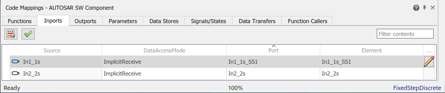
In1_1s, the AUTOSAR receiver port to which the Simulink inport was mapped. An attributes panel appears, showing the attributes settings for that element.In the AUTOSAR Dictionary, rename the AUTOSAR receiver port
In1_1stoIn1_1s_SS1. To initiate the edit, double-click the Name value field.The Code Mappings editor reflects the name change.
Save the model.
Next, simulate the AUTOSAR software component.