Guided Weapons Evaluation Facility Replaces Missile Testing System
“MathWorks tools are our long-term testing solution for the facility. We are in the process of converting our Fortran-based systems to Simulink for hardware-in-the-loop testing using Simulink Real-Time.”
Challenge
Solution
Results
- Simulation time reduced by 300%
- Team collaboration achieved
- Development time reduced by two months

Before missiles are deployed in combat, they must pass a number of stringent tests to ensure they will operate consistently and as intended. Performing real-time hardware-in-the-loop (HIL) tests of weapon systems helps the military evaluate performance by simulating environmental conditions and determining how weapons would respond during actual flights.
The U.S. Air Force’s Guided Weapons Evaluation Facility (GWEF) chose MathWorks tools to design and run real-time simulations for testing and evaluating air armament systems. After conducting a side-by-side test bed comparison, GWEF is replacing their existing Fortran-based HIL testing systems with systems based on Simulink® and Simulink Real-Time™.
“The simulations ran three times faster using Simulink Real-Time,” says Kenneth Anthony, GWEF technical director. “Based on the performance of our first endeavor, we’ve decided to replace our systems based on Fortran with Simulink Real-Time.”
Challenge
GWEF sought to modernize their testing systems with software that would enable them to develop real-time HIL simulations using off-the-shelf PC hardware.
“Our customers increasingly expect higher fidelity modeling and data,” explains Anthony. “As our models grow, it becomes harder to maintain the required frame rates with our current systems. The idea was to achieve higher fidelity simulations with high frame rates and low costs using off-the-shelf technology.”
They also sought to reduce the development and debugging time and enable their engineers to focus more on system-level design rather than programming. The engineers sought a software development environment that could automatically generate production code and did not require them to write device-level drivers, which can be time consuming and difficult to maintain.
“We spent many years optimizing our Fortran code to run fast,” explains Anthony. “We were skeptical that automatically generated code could run faster than our hand code in real time.”
Because GWEF would need to conduct a test from a remote location that is not conducive to simulation development, they needed to design a portable system in the test facility that they could transport to the test site.
“Our legacy computers are bulky and require a lot of cabling and routing, so they’re not exactly portable,” explains Anthony.
Finally, GWEF would seek to demonstrate their results to customers in a visual environment and to show that discrepancies in the data could be quickly identified.

Solution
After conducting an industry-wide survey of numerous software packages, GWEF chose MathWorks tools to develop their testing system for the Operational Ground Test (OGT) project for the U.S. Air Force. This proof-of-concept involves removing a weapon out of inventory and simulating the effects of the missile from launch through guided flight, complete with engine burn.
After performing a side-by-side comparison with their existing system, they discovered that the new system built with MathWorks tools reduced simulation times.
For OGT, GWEF developed their models using Simulink block diagrams, automatically generated code with Simulink Coder™, and then executed the code on PC hardware using Simulink Real-Time. The results were then validated against an existing Fortran simulation that had been proven against real-world data.
Designing System Models
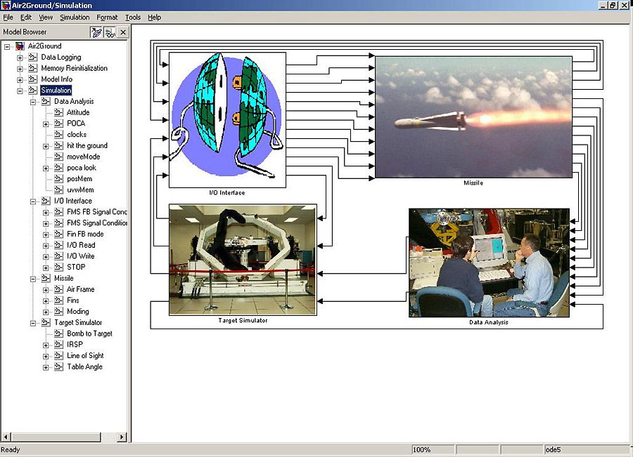
The test system consisted of a target and a missile. GWEF replicated the Fortran code from the original system by creating equivalent models with Simulink and Stateflow ®. The missile model contained subsystems that represented each of the major parts of the missile, which were placed in association with each other and their associated environmental effects. They used Aerospace Blockset ™ to model these conditions and the six-degrees-of-freedom equations of motion.
They used Simulink to recreate most of the functionality represented by Fortran code. GWEF modeled the actuators using Simulink transfer function blocks.
Using the missile model as a guide, a physicist then built a digital seeker model. With the graphical nature of Model-Based Design, GWEF easily integrated the seeker model with the other subsystems of the missile model. Other engineers also used the model for hardware integration.
“Despite having very little experience with Simulink, our engineers came up to speed within a couple of days and even improved the design,” says Anthony.
Generating Code and Running Hardware-in-the-Loop Simulations
They used Simulink Coder to automatically generate C code from their Simulink diagrams. Using Simulink Real-Time, they created an HIL simulation testing environment.
GWEF ran simulations in digital mode with Simulink, then transferred them to Simulink Real-Time. The simulations ran exactly the same except that they used real I/O from the hardware.
“The host-target relationship with Simulink Real-Time was ideal for this project,” explains Ethan Woodruff, a systems analyst at BAE Systems, who helped develop the new simulation for GWEF.
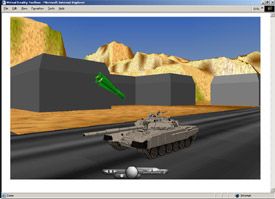
Using Simulink 3D Animation™, GWEF simulated the launching of the missile from the aircraft in a 3D animation viewer.
“For the test, it was important to not only show the missile, but also be able to observe the missile rolling, pitching, and yawing—all together in real time,” explains Anthony. “Simulink 3D Animation provides one of the best simulation monitoring tools in the facility and enables our audience to view the simulation in a visual environment as it runs.”
Performing Data Analysis
After the simulation, they brought the data into MATLAB ® from Simulink Real-Time over Ethernet and created plots for identifying and analyzing discrepancies in data. In future applications, this data will be combined with data acquired from other sources using Data Acquisition Toolbox™.
“Before, we had to examine reams of paper to compare data sets,” says Anthony. “Now that the simulation is integrated with MATLAB, we can perform data analysis more quickly. We converted just about all of our older data acquisition systems to systems using Data Acquisition Toolbox, and our engineers are thrilled.”
With favorable results, GWEF plans to use the new system in a real-world operational test of two inert weapons, which will include the firing of the missile rocket motors.
Results
- Simulation time reduced by 300%. Simulation main loop time ran three times faster than with their previous hardware, with more speed increase possible from faster processors in the future.
- Team collaboration achieved. “Many of our customers design with MathWorks products, so we can share models and information with them,” explains Anthony. “This creates a more efficient process.”
- Development time reduced by two months. “It would have taken a minimum of two months to develop specific hardware and device drivers in Fortran,” notes Anthony. “With Simulink Real-Time, we don’t have to worry about that anymore because we have a supportable and maintainable system and architecture that lets our engineers focus on creating simulations instead of debugging syntax errors.”
