What Is LQR Optimal Control? | State Space, Part 4
From the series: State Space
Brian Douglas
LQR is a type of optimal control based on state-space representation. In this video, we introduce this topic at a very high level so that you walk away with an understanding of the control problem and can build on this understanding when you are studying the math behind it. This video will cover what it means to be optimal and how to think about the LQR problem. At the end, I’ll show you some examples in MATLAB® that will help you gain a little intuition about LQR.
Published: 7 Mar 2019
Let’s talk about the Linear Quadratic Regulator, or LQR control. LQR is a type of optimal control that is based on state-space representation. In this video, I want to introduce this topic at a very high level so that you walk away with a general understanding of the control problem and can build on this understanding when you are studying the math behind it. I’ll cover what it means to be optimal, how to think about the LQR problem, and then I’ll show you some examples in MATLAB that I think will help you gain a little intuition about LQR. I’m Brian, and welcome to a MATLAB Tech Talk.
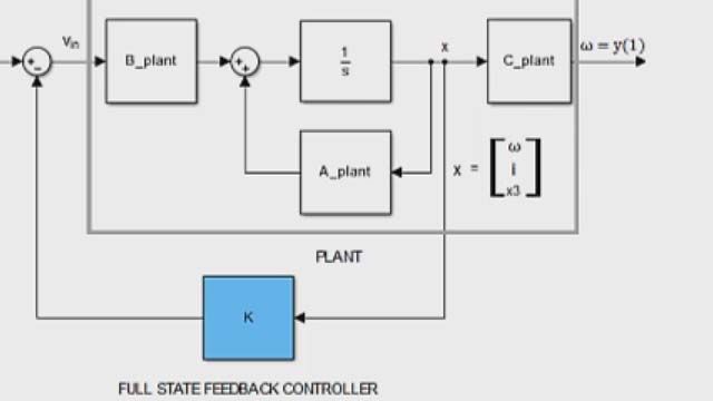
To begin, let’s compare the structure of the pole placement controller that we covered in the second video and an LQR controller. That way you have some kind of an idea of how they’re different. With pole placement, we found that if we feed back every state in the state vector and multiply them by a gain matrix, K, we have the ability to place the closed-loop poles anywhere we choose, assuming the system is controllable and observable. Then we scaled the reference term to ensure we have no steady state reference tracking error.
The LQR structure, on the other hand, feeds back the full state vector, then multiplies it by a gain matrix K, and subtracts it from the scaled reference. So, as you can see, the structure of these two control laws are completely diff—well, actually, no, they’re exactly the same. They are both full-state feedback controllers and we can implement the results with the same structure from both LQR and pole placement.
A quick side note about this structure: We could have set it up to feed back the integral of the output or we could have applied the gain to the state error. All three of these implementations can produce zero steady state error and can be used with the results from pole placement or LQR. And if you want to learn more about these other two feedback structures, I left a good source in the description.
Okay, we’re back. So why are we giving these two controllers different names if they are implemented in the exact same way? Well, here’s the key. The implementation is the same, but how we choose K is different.
With pole placement, we solved for K by choosing where we want to put the closed-loop poles. We wanted to place them in a specific spot. This was awesome! But one problem with this method is figuring out where a good place is for those closed-loop poles. This might not a terribly intuitive answer for high-order systems and systems with multiple actuators.
So with LQR, we don’t pick pole locations. We find the optimal K matrix by choosing closed-loop characteristics that are important to us—specifically, how well the system performs, and how much effort does it take to get that performance. That statement might not make a lot of sense so let’s walk through a quick thought exercise that I think will help.
I’m borrowing and modifying this example from Christopher Lum, who has his own video on LQR that is worth watching if you want a more in-depth explanation of the mathematics. I’ve linked to his video in the description. But here’s the general idea:
Let’s say you’re trying to figure out the best way or the most optimal way to get from your home to work. And you have several transportation options to choose from. You could drive your car, you could ride your bike, take the bus, or charter a helicopter. And the question is, which is the most optimal choice? That question by itself can’t be answered because I haven’t told you what a good outcome means. All of those options can get us from home to work, but they do so differently and we need to figure out what’s important to us. If I said time is the most important thing, get to work as fast as possible, then the optimal solution would be to take the helicopter. On the other hand, if I said that you don’t have much money and getting to work as cheaply as possible was a good outcome, then riding your bike would be the optimal solution.
Of course, in real life you don’t have infinite money to maximize performance and you don’t have unlimited time to minimize spending, but rather you’re trying to find a balance between the two. So maybe you’d reason that you have an early meeting and therefore value the time it takes to get to work, but you’re not independently wealthy, so you care about how much money it takes. Therefore, the optimal solution would be to take your car or to take the bus.
Now if we wanted a fancy way to mathematically assess which mode of transportation is optimal, we could set up a function that adds together the travel time and the amount of money that each option takes. And then we can set the importance of time versus money with a multiplier. We’ll weight each of these matrices based on our own personal preferences. We’ll call this the cost function, or the objective function, and you can see that it’s heavily influenced by these weighting parameters. If Q is high, then we are penalizing options that take more time, and if R is high, then we are penalizing options that cost a lot of money. Once we set the weights, we calculate the total cost for each option and choose the one that has the lowest overall cost. This is the optimal solution.
What’s interesting about this is that there are different optimal solutions based on the relative weights you attach to performance and spending. There is no universal optimal solution, just the best one given the desires of the user. A CEO might take a helicopter, whereas a college student might ride a bicycle, but both are optimal given their preferences.
And this is exactly the same kind of reasoning we do when designing a control system. Rather than think about pole locations, we can think about and assess what is important to us between how well the system performs and how much we want to spend to get that performance. Of course, usually how much we want to spend is not measured in dollars but in actuator effort, or the amount of energy it takes.
And this is how LQR approaches finding the optimal gain matrix. We set up a cost function that adds up the weighted sum of performance and effort overall time and then by solving the LQR problem, it returns the gain matrix that produces the lowest cost given the dynamics of the system.
Now the cost function that we use with LQR looks a little different than the function we developed for the travel example, but the concept is exactly the same; we penalize bad performance by adjusting Q, and we penalize actuator effort by adjusting R.
So let’s look at what performance means for this cost function. Performance is judged on the state vector. For now, let’s assume that we want every state to be zero, to be driven back to its starting equilibrium point. So if the system is initialized in some nonzero state, the faster it returns to zero, the better the performance is and the lower the cost. And the way that we can get a measure of how quickly it’s returning to the desired state is by looking at the area under the curve. This is what the integral is doing. A curve with less area means that it spends more time closer to the goal than a curve with more area.
However, states can be negative or positive and we don’t want negative values subtracting from the overall cost, so we square the value to ensure that it’s positive. This has the effect of punishing larger errors disproportionately more than smaller ones, but it’s a good compromise because it turns our cost function into a quadratic function. Quadratic functions, like z = x^2 + y^2 are convexed, and therefore, have a definite minimum value. And quadratic functions that are subject to linear dynamics remain quadratic so our system will also have a definite minimum value.
Lastly, we want to have the ability to weight the relative importance of each state. And therefore, Q isn’t a single number but a square matrix that has the same number of rows as states. The Q matrix needs to be positive definite so that when we multiply it with the state vectors, the resulting value is positive and nonzero. And often it’s just a diagonal matrix with positive values along the diagonal. With this matrix, we can target the states where we want really low error by making the corresponding value in the Q matrix really large, and the states that we don’t care about as much make those values really small.
The other half of the cost function adds up the cost of actuation. In a very similar fashion, we look at the input vector and we square the terms to ensure they’re positive, and then weight them with an R matrix that has positive multipliers along its diagonal.
We can write this in larger matrix form as follows, and while you don’t see the cost function written like this often, it helps us visualize something. Q and R are part of this larger weighting matrix, but the off diagonal terms of this matrix are zero. We can fill in those corners with N, such that the overall matrix is still positive definite but now the N matrix penalizes cross products of the input and the state. While there are uses for setting up your cost function with an N matrix, for us we’re going to keep things simple and just set it to zero and focus only on Q and R.
So by setting the values of Q and R, we now have a way to specify exactly what’s important to us. If one of the actuators is really expensive and we’re trying to save energy, then we penalize it by increasing the R matrix value that corresponds with it. This might be the case if you’re using thrusters for satellite control because they use up fuel, which is a finite resource. In that case, you may accept a slower reaction or more state error so that you can save fuel.
On the other hand, if performance is really crucial, then we can penalize state error by increasing the Q matrix value that corresponds with the states we care about. This might be the case when using reaction wheels for satellite control because they use energy that can be stored in batteries and replenished with the solar panels. So using more energy for low-error control is probably a good tradeoff.
So now the big question: How do we solve this optimization problem? And the big disappointing answer is that deriving the solution is beyond the scope of this video. But I left a good link in the description if you want to read up on it.
The good news, however, is that as a control system designer, often the way you approach LQR design is not by solving the optimization problem by hand, but by developing a linear model of your system dynamics, then specifying what’s important by adjusting the Q and R weighting matrices, then running the LQR command in MATLAB to solve the optimization problem and return the optimal gain set, and then just simulate the system and adjust Q and R again if necessary. So as long as you understand how Q and R affects the closed-loop behavior, how they punish state errors and actuator effort, and you understand that this is a quadratic optimization problem, then it’s relatively simple to use the LQR command in MATLAB to find the optimal gain set.
With LQR, we’ve moved the design question away from where do we place poles, to the question, how do we set Q and R. Unfortunately, there isn’t a one-size-fits-all method for choosing these weights; however, I’d argue that setting Q and R is more intuitive than picking pole locations. For example, you can just start with the identity matrix for both Q and R and then tweak them through trial and error and intuition about your system. So, to help you develop some of that intuition, let’s walk through a few examples in MATLAB.
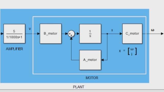
All right, this needs a little explanation. Let’s start with the code. I have a very simple model of a rotating mass in a frictionless environment and the system has two states, angle and angular rate. I’m designing a full-state feedback controller using LQR, and it really couldn’t be simpler. I’ll start with the identity matrix for Q where the first diagonal entry is tied to the angular error and the second is tied to angular rate. There is only a single actuation input for this system, which are four rotation thrusters that all act together to create the single torque command. Therefore, R is just a single value.
Now I solve for the optimal feedback gain using the LQR command and build a state-space object that represents the closed-loop dynamics. With the controller designed, I can simulate the response to an initial condition, which I’m setting to 3 radians. That’s pretty much the whole thing. Everything else in this script just makes this fancy plot so it’s easier to comprehend the results.
Okay, let’s run this script. You can see the UFO gets initialized to 3 radians as promised. Up at the top I’m keeping track of how long the maneuver takes which is representative of the performance, and how much fuel is used to complete the maneuver. So let’s kick it off and see how well the controller does.
Look at that, it completed the maneuver in 5.8 seconds with 15 units of fuel and got the cow in the process, which is the important part. When the thrusters are active, they generate a torque that accelerates the UFO over time. Therefore, fuel usage is proportional to the integral of acceleration. So the longer we accelerate, the more fuel is used.
Now let’s see if we can use less fuel for this maneuver by penalizing the thruster more. I’ll bump R up to 2 and rerun the simulation.
Well, we used 2 fewer units of fuel, but at the expense of over 3 additional seconds. The problem is that with this combination, it overshot the target just a bit and had to waste time coming back. So let’s try to slow down the max rotation speed with the hope that it won’t overshoot. We’re going to do that by penalizing the angular rate portion of the Q matrix. Now, any non-zero rate costs double what it did before. Let’s give it a shot.
Well, we saved about a second since it didn’t overshoot, and in the process managed to knock off another unit of fuel. All right, enough of this small stuff. Let’s really save fuel now by relaxing the angle error weight a bunch.
Okay, this going really slowly now. Let me speed up the video to just get through it. In the end, we used 5 units of fuel, less than half of what was used before. And we can go the other way as well and tune a really aggressive controller.
Yes, that’s much faster. Less than 2 seconds and our acceleration is off the charts. That’s how you rotate to pick up a cow. Unfortunately, it’s at the expense of almost 100 units of fuel, so there’s down sides to everything. All right, so hopefully, you’re starting to see how we can tweak and tune our controller by adjusting these two matrices. And it’s pretty simple.
Now, I know this video is dragging on, but with a different script I want to show you one more thing real quickly, and that’s how LQR is more powerful than pole placement. Here, I have a different state-space model, one that has three states and a single actuator. I’ve defined my Q and R matrices and solved for the optimal gain. And like before, I’ll generate the closed-loop state-space model and then run the response to an initial condition of 1, 0, 0. I then plot the response of the first state, that step from 1 back to 0; the actuator effort; and the location of the closed-loop poles and zeroes.
So let’s run this and see what happens. Well, the first state tracks back to 0 nicely, but at the expense of a lot of actuation. I didn’t model anything in particular but let’s say the actuator effort is thrust required. So this controller is requesting 10 units of thrust. However, let’s say our thruster is only capable of 2 units of thrust. This controller design would saturate the thruster and we wouldn’t get the response we’re looking for. Now, had we developed this controller using pole placement, the question at this point would be which of these three poles should we move in order to reduce the actuator effort? And that’s not too intuitive, right?
But with LQR, we can easily go to the R matrix and penalize actuator usage by raising a single value. And I’ll rerun the script. We see that the response is slower, as expected, but the actuator is no longer saturated. And, check this out, all three closed-loop poles moved with this single adjustment of R. So if we were using pole placement, we would have had to know to move these poles just like this in order to reduce actuator effort. That would be pretty tough.
So that’s where I want to leave this video. LQR control is pretty powerful and hopefully you saw that it’s simple to set up and relatively intuitive to tune and tweak. And the best part is that it returns an optimal gain matrix based on how you weight performance and effort. So it’s up to you how you want your system to behave in the end.
If you don’t want to miss the next Tech Talk video, don’t forget to subscribe to this channel. Also, if you want to check out my channel, Control System Lectures, I cover more control theory topics there as well. Thanks for watching. I’ll see you next time.


