Rapid Prototyping of Embedded Designs Using NXP Model-Based Design Toolbox - MATLAB & Simulink
Video Player is loading.
Current Time 0:00
Duration 20:16
Loaded: 0.00%
Stream Type LIVE
Remaining Time 20:16
 
1x
  • Chapters
  • descriptions off, selected
  • en (Main), selected
    Video length is 20:16

    Rapid Prototyping of Embedded Designs Using NXP Model-Based Design Toolbox

    Irina Costachescu, NXP Semiconductors
    Marius Lucian Andrei, NXP Semiconductors

    Get to know NXP Model-Based Design Toolbox™—a connection between MathWorks and NXP ecosystems that allows rapid prototyping of complex embedded designs on NXP microcontrollers.

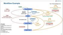
    The Model-Based Design Toolbox can be used throughout all the application development phases, starting from an idea all the way to the final solution deployment.

    Its integration with the rich MathWorks ecosystem allows modeling ideas into Simulink® designs, while enhancing the Model-Based Design paradigm key advantages such as simulation, verification and validation, automatic code generation, and reusability. It also provides a streamlined way to run embedded applications on NXP microcontrollers by integrating and linking target-specific software like drivers and libraries to Simulink applications. It also enables the cross-compilation of Simulink generated code and its download to the microcontrollers.

    Such embedded applications can range across multiple domains like automotive, industrial and IoT, and can cover specific tasks like motor control, car access, lighting, or battery powered solutions.

    If we talk about battery-powered applications, like electric vehicles or grid energy storage, battery management systems (BMS) play a key role in the optimal and safe power usage of the rechargeable cells. With MATLAB® and Simulink, BMS can be designed under safe conditions, from logic control states to complex functionalities like the state of charge (SOC) estimation. This task can be completed either based on traditional methods or by relying on data driven models using artificial intelligence. Once the simulation results are satisfying, the NXP Model Based Design Toolbox can deploy the BMS applications directly from Simulink on embedded targets. By using NXP Simulink blocks, the users can control the microcontroller peripherals, and also extend the hardware commands up to the analog front end, the NXP battery cell controllers.

    In this presentation, we will highlight the main features of the NXP Model-Based Design Toolbox. We will demonstrate how to design a BMS application, covering the main development phases from idea to a prototype running on target.

    Published: 29 May 2022

    Hello, everyone, and welcome to our session. We are Irina Costachescu and Marius Andrei, software engineers at NXP Semiconductors. And today we would like to show you how you can translate ideas into embedded designs fast and efficient directly from Simulink using NXP's Model-Based Design Toolbox. Let's see exactly what this means.

    First, we will briefly introduce you to NXP and the ecosystem of solutions it provides. Then, we'll get to know the Model-Based Design Toolbox for MATLAB Simulink and see how it integrates into such a battery management system design.

    But before diving into this, let's get to know NXP, a company with more than 60 years into the semiconductors manufacturing and design business, which provides solutions for anticipating and automating people's needs. In a world which contains billions of interconnected devices linked to the Cloud's large processing power and its millions of data centers, NXP contributes, through its technologies, to environmental and life quality improvements.

    From the fast access to services directly from our smartphones all the way to smart city solutions, robots, and machines in the industrial domains, NXP addresses challenges where performance and reliability are critical. NXP also continuously improves the automotive area, providing safety to our relationship to transport through its focus on advanced driver assistance systems, supporting as well the electrification changes as an alternative to combustion engine cars.

    To keep all these solutions connected and integrated in our world in a fast and reliable manner, a large processing power is required, offered by annex NXP through the applications and devices it delivers. But how can we implement such innovative technologies to work on NXP microcontrollers?

    All NXP processors provide impressive computing power with a low power consumption envelope and a rich selection of peripherals. For its hardware, NXP delivers optimized software, facilitating the hardware access, documentation, and reference designs all for reducing the complexity of the applications development process. On top of these, a variety of tools allows our customers to move fast from ideas to running on target designs.

    NXP's IDEs integrate numerous functionalities, like build tools for transforming application code into executable files and debugger tools where features such as registers view allow monitoring changes at each step of the process. Configuration tools allow setting and initializing the hardware components used by the embedded design in a graphical manner, while also generating C code for the selected options.

    Peripherals can be set via drop down menus, having all the necessary documentation integrated into this interface. Similarly the processors pins can be configured in a graphical manner, while clock settings, enablement, and routing are available options, as well.

    So using the NXP ecosystem, applications can be developed and downloaded on hardware without leaving the IDE since this integrates all the necessary software and tools for creating embedded designs. Moreover, besides the classical debugger options, NXP provides a data visualization tool that allows real time applications debug, allowing to monitor signals on the embedded target, both in an oscilloscope-like display or in text form.

    Such a tool can be also used to build quick demos incorporating the option of designing intuitive user interfaces. This tool is called free master, and it ensures a bidirectional communication with the embedded system to check the status of the application at any moment.

    So using NXP ecosystem applications can be designed, prototyped by writing C code, validated on target, and then deployed as a final solution-- the classical way of doing programming. However, this classical sequential flow implies that the testing part comes at the end when the application is already running on the target-- fact which could prevent errors to be detected early during the development process.

    Yet, on top of all these, NXP provides the Model-Based Design Toolbox for rapid prototyping ideas into running on target applications. The product includes all the sources necessary to generate and download code on NXP specific platforms directly from Simulink. The Model-Based Design Toolbox comes as a gateway between The MathWorks and the NXP ecosystems, leveraging the model-centric applications development benefits and incorporating features like simulation, code generation, verification, and validation in the context of embedded systems design.

    While adopting this approach, the flow of translating ideas into running on target applications modifies. Since functionalities can be now tested and integrated at each phase of the development process, given the continuous verification capabilities Simulink provides. Hence, reliability into the designs can be gained through simulation prior to their deployment on target, which brings into discussion a reduced time to market and also an increased degree of algorithms re-usability across hardware platforms.

    MBDT can be used for a wide range of embedded applications, providing the suite of products for various NXP MCUs. It covers a large portfolio of automotive hardware platforms while having also packages suitable for processors targeting industrial and IoT designs, as well. Computer vision and machine learning solutions prototyping can be achieved using MBDT for vision, while radar applications are addressed by the support offered for the R41 platform.

    Moreover, MBDT can also be integrated with other tools for building more complex solutions. For example, to get a glimpse on such an use case you could watch the automotive dev ops for model-based design with Amazon Web Services session held at this expo edition to see how MBDT can be integrated with MathWorks and AVS tools to design a cloud to vehicle solution targeting NXP's vehicle network processors.

    And since you may still wonder why is the need of an additional toolbox to use MATLAB and Simulink with NXP MCUs, let's dive into some more details on the software development environment. For creating embedded designs, besides MATLAB and Simulink, customers need to translate models and scripts into C code. And the embedded MATLAB and Simulink coders are necessary for achieving this task.

    Optional toolboxes can also be used for addressing design particularities and improve your productivity. Hence, MathWorks provides already an entire set of tool boxes that help customers move quickly from ideas to application C code.

    But these need a final link-- the specific support to be able to customize and deploy the algorithms on specific hardware. And this is where MBDT, with all its modules and functionalities integrated inside this MathWorks ecosystem, comes in to help. Let's get a quick overview of these and see what is delivered within this product package.

    MBDT integrates hardware optimized drivers for configuring and controlling the MCU peripherals and libraries designed for specific targets and applications purposes. Together with these, it provides access to configuration tools that allow setting and initializing the hardware in accordance to the design's particularities. The build tools it incorporates enable the cross compilation of the Simulink applications generated code with such target specific software and the deployment to the MCU.

    For controlling and interacting with the hardware, MBDT delivers a library of Simulink blocks which implement functionalities of MCU peripherals and that can be used to make model algorithms hardware aware generating code on top of specific drivers functions. And to see exactly how MBDT operates, a set of ready to run simulating applications exemplify all of its features like simulation, verification, and validation functionalities, supported peripherals operating modes, and much more.

    Now that we have seen what this solution represents and why it is used, I'm going to pass it to Marius to introduce you to the MBDT applications development flow exemplified on a battery management system design.

    Thank you, Irina, and hello to everyone. If we talk about battery powered applications like electric vehicles or grid energy storage, battery management systems-- BMS-- plays a key role in the optimal and safe power usage of the rechargeable cells. In the next few minutes, we will see how a BMS can be designed under safe conditions and from logic control states to complex functionalities like the state of charge estimation.

    Every application starts from one idea. In this stage, we define our control system and software requirements. Based on the chosen architecture, we can start to implement and test specific subsystems of our application like we can see here, the state of charge estimation. Then these subsystems can be integrated together into our BMS application.

    We can have the main state machine, which operates our BMS through different running states. We can integrate the SOC estimator, and also we can integrate the balance in logic. The entire application can later be connected to a battery plant model and tested under various and different scenarios.

    Now that we have the BMS application developed in Simulink we can prepare our models for code generation. SIL, the Software In the Loop, comes as an important test, providing us useful information on how the Simulink model is translated into C code. This process shows the result accuracy of the generated code, creating the context for algorithm optimization and for efficiency improvements.

    For the system under test, we can apply the same input vectors as for the model in the loop. Simulink can automatically compare the results obtained by these two simulation models. A code generation report [INAUDIBLE] during the SIL process showing us the generated code and different metrics of the execution.

    Up to this point, we have developed the BMS application without touching any embedded processor. Now it's time to start testing our design on an MCU. The next step is the processor in the loop. PIL behaves mostly similar like SIL test, but the major difference here is that the generated code is now executed on an embedded processor.

    We generate the same C code for the application, but this time we cross compile the generated code into an executable file, which is deployed on the microcontroller. For this kind of test, we can use an evaluation board, because for this step what we are testing is how the algorithm runs on hardware. This test provides information about the memory consumption and the execution time on the MCU.

    So what we can see here is the open look execution in PIL mode of a neural network algorithm for the state of charge estimation. If you are interested in this particular topic and you want to learn how to integrate AI models into model-based design, please attend the Integrating AI-based Virtual Sensors Into Model-based Design session of this MATLAB Expo.

    Now that we have validated our design and concluded that the performance of our application respects our requirements, it is time to run our Simulink model on an embedded system and connect our design to our battery pack. To accelerate the BMS project development, NXP provides a high voltage battery management system reference design, a scalable ICLD architecture composed of multiple modules.

    The smallest unit in this puzzle is the battery cell. To reach to the power required for supplying our application, we can connect together multiple batteries into modules, resulting in our battery pack. Each of these battery modules has to be connected to a cell monitoring unit. The CMU can measure parameters like voltages, temperatures, and can balance our battery cells.

    We can redundantly measure our battery packs current and several other high voltage values on the battery pack using the NXP battery junction box. All these devices can be connected to a battery management unit through a robust transformer physical layer protocol-- the TPL. The battery management unit is the brain of the BMS, containing an NXP processor, which runs the BMS application code generated from our Simulink model with the help of the MBDT Toolbox.

    Besides the communication with all these modules, an outside communication with the car system, the BMU also drives the contactors. Their role is to connect the battery pack to the load, or to the charger, or to rapidly disconnect the pack in case of emergencies.

    With all this setup in mind, we can now move to the development desk. Here, we can replace the battery cells with the cell emulator. This can help us to quickly drive our system under critical scenarios, like low or high voltage, without damaging a real battery pack, but most important to keep everything under safe conditions.

    On the main screen, we have our BMS Simulink model. If we want to configure the microcontroller peripherals, we can launch an external configuration tool directly from our model and have access to all the microcontroller settings. Once we are done with the configuration, we can get back to Simulink. And with a click of a button, our model becomes aware of the hardware changes we've just made.

    From this model, the entire application C code can be automatically generated, built into a binary file, and deployed on MCU using an external debug adapter. Once our generated code is running on our prototype, we can monitor and visualize our data in real time, or we can send some commands to the MC application using the NXP FreeMASTER. With this tool, we can also send data from our BMS system back to MATLAB for further analysis.

    Let's zoom into our design. We have here our BMS application passed through all the verification and validation steps and the blocks from the NXP Model-Based Design Toolbox. During the integration process, we can keep the Simulink algorithm hardware independent, just like using a black box. We connect the MBDT block switch inputs and outputs for making it harder aware.

    BMS algorithms input can be fed either from MCUs peripherals, external devices, or communication. The outputs of the BMS algorithm can be sent to the MCU over CAN or the balancing commands can be sent directly to the CMU. In case we need to do some hardware specific initialization process, we can add some blocks as we did here on the top of the model.

    To monitor our application behavior, we could make use of the FreeMASTER support MBDT integrates by adding the FreeMASTER config Simulink block from our library. Once the code is running on our prototype, with FreeMASTER we can create the graphical user interface for monitoring or control our application. Instead of using scopes only or looking directly to values, we can put this kind of dashboards together by using technologies like HTML5 or JavaScript.

    In this particular example, we choose to have a main page summarizing the state of our battery pack, the pack voltage, the current, the state of charge, or full stops. On other tabs the user can check particular parameters for each cell or set the right settings for the application without the need of regenerating the dashboard again.

    Now if you are interested to speed up your work using the NXP ecosystem in MATLAB in a similar way we've just presented, you can install our toolboxes directly from MATLAB Addons, or of course you can download them from the NXP website. All the toolboxes are free of charge.

    If you have questions, feedback for us, or encounter any issues, you can open a thread on our MBDT community space. Here you can discuss directly with the engineers behind these toolboxes. You can also follow our trainings and courses, like the beginner's guide series or even more particular application demos focusing BMS, Autosar or motor control.

    Moreover, you could also nxp.com for more details on the development ecosystem NXP provides. Thank you very much for your time and attention. And if you would like to chat more about NXP solutions, you can find us in the booth ready to answer questions and provide additional details.

    View more related videos