Accelerating Safe Railway Application Development Using Model-Based Design
Daran Smalley, Alstom
Alstom’s train traction team uses MATLAB® and Simulink® to develop traction control software adhering to Software Safety Level 2 standard EN 50657 (including former EN 50128).
Hear a brief summary of the earlier talk from MATLAB EXPO 2018 when the traction control team used MATLAB and Simulink for prototyping code generation on traction controllers for the very first time. Learn how Alstom transformed its software development processes and tools from traditional tools such as Visio, textual documents in combination with IEC 1131 design tools, and hardware-based testing using MATLAB and Simulink for requirement management, software development, and verification on personal laptops according to safety standards EN 50128/50657. Alstom has developed software products and projects to successfully have trains running in passenger service with independent safety assessment using a Model-Based Design certified workflow from MathWorks. Alstom upskilled its software developers and verifiers to transform into this new way of working and new tools. For certain validation activities, the team has managed to cut cost by 80% compared to traditional way of working.
Hear about the opportunities Alstom sees in MATLAB and Simulink and what the team is prototyping to create an even more efficient system development process. Learn about some of the challenges faced and how to overcome them, as such transformations don’t always go smoothly.
Published: 3 May 2023
[MUSIC PLAYING]
Welcome. Today, I'm going to be presenting Accelerating Safe Railway Application Development Using Model-Based Design. I'm Daran Smalley. I work as a brake subsystem manager at Alstom.
Today, I'll run you through quickly a bit about us, Alstom, what we see as the global trends in the railway industry, our traditional workflow and our updated workflow with the model-based design, and how we see the future of model-based design withinside Alstom.
A bit about us. Alstom is mobility by nature. So we're striving to find the greenest and smartest mobility solutions for the world.
Alstom is quite a large company. A very, very large global footprint here, where we're 74,000 employees worldwide. We're a bit under 20,000 engineers, where we have around 150,000 vehicles in commercial service today.
We supply multiple solutions, different rolling stock, signaling and infrastructure, services and turnkey solutions, performing all those for one customer.
Where I'm stationed in Vasteras, we're supporting Alstom with the rolling stock and components. So this is our full traction systems that can go up to about four megawatts. Inside Vasteras, we have power labs, where we're able to verify that these converter boxes and the motors work as intended up to their full power range. So up to the full four megawatts.
We're continuously developing and improving. And inside Vasteras, we're also introducing the brakes department. The brakes department will then be developing and testing the brake systems to run on the future Alstom trains.
About myself, I'm a mechatronics engineer from Monash University in Melbourne, and now enjoying the freezing cold in Sweden. Before moving here, I spent three years as an electrical engineer at Rio Tinto's smelter, automating some of their cranes.
I took a gap year traveling around Europe, and I loved it so much that I decided to stay. And I've been spending seven years in Vasteras, working as a traction control engineer. In that role, I've been doing a range of things, from train performances, customer face-to-face, and introducing the model based design way of working into the traction team.
What we see is Alstom as a global trend is digitization, looking at a seamless journey of mobility, reducing our emissions, having globalization too, urbanization of towns and cities, and showing we consider the environment in any change we do, how everything is connected, but most importantly, safety. Safety is always our top priority.
As we are seeing more and more changes in the world, we notice there's a growing complexity, and especially from the software. What we noticed is that the software complexity is exponentially increasing. So the software development productivity needs to catch up. And small incremental changes is not quick enough to match software complexity that we're seeing today. So we needed to revolutionize the way we think.
So we had our traditional workflow before our introduction of model-based design. The typical design process was receiving the requirements from a customer, breaking them down into the control, mechanical and electrical domains. From the design, from the control perspective, we'll then pass it over to be implemented so it can work on a target controller. Once it's on a target controller, it can finally be integrated and tested. So it's the first time you're verifying the implementation, the design, and the requirements.
Given the way of working through the departments and the tools, we didn't find an easy way of bringing control, mechanical electrical together until the final integration and test. So everyone's working in silos. Between the control and implementation, there was a manual implementation step, which is slow and buggy.
Mechanically and electrically, the first time that we were able to verify these designs was in the integration test phase. It was very hard to prototype these solutions in a quick, agile way. And the requirements, we didn't have any formal ways of verifying our requirements. They were only verified in the final integration test phase.
So as you imagine, what this meant for us in a standard project was that we received the requirements from a customer. We'll take those requirements. We'll break it down. We'll have our design. We'll do the implementation. We'll do the build. And then we'll start the verification process.
And since we're human, we made mistakes. We didn't capture everything. And this has cost a lot of time and money. So we had to take those verification information and then update our design, but then we also had to do another build so we could say everything integrated together and verify the build again.
The build still didn't meet our customer requirements, so we had to do another round of design and build. And whilst it wasn't exactly as required, it was what the customer desired. So it finally passes verification. So this is a very long process and it's a very costly process, doing this continuous build and slow feedback loops.
So a few years ago, when we introduced the model-based design way of working, the focus was on modeling, instead of documenting, and failing fast, trying to find out these issues a lot earlier. What this meant was, in a practical sense, when we developed our control code and our design, we used embedded coder to generate the code, removing the manual implementation step.
And so in the design step, the mechanical and electrical and control could start working together inside one environment. This enabled a simulation environment to simulate control, mechanical, electrical together. So this means you could do some design assurance before the first integration and test.
Since you've got the mechanical and electrical designs in your simulation environment, you can also generate and run them on your hardware-in-the-loop rigs as well. And from a requirements perspective, since you can then start linking your requirements to the design and you can have a simulation, you can start verifying designs, your requirements a lot earlier.
So when we introduced this way of working, failing fast, using a similar example, we were using models. So went from requirements into the model, and then we verified the model. It was a lot quicker than doing the build, so we found the issues a lot earlier. When we found the issue, we did another model. We verified that model. We noticed that we still have some more issues, so we created a new model, verified the next model, and realized that model now is going to work as the customer needs.
So then we go into the next step, which is in the designing for manufacturing. Then we did the build and we did the last round of verification. So as you see, there is more steps involved, but they're a lot quicker. So the total process is a lot less than the traditional way of working. So you're saving time and money by using these models and early verification compared to the traditional approach.
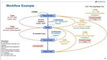
So this approach, in the case of software, is a V model inside the rail industry. So we had the EN 50128 and EN 50657 both recommend a software development process. And it highlights it in a V model, as you see in front of you. All this V model demonstrates is that you should start with the requirements and they should be broken down into the software architecture and design.
After there, you make the components. And once you've made the components, you start the component implementation. Once the components are implemented, you verify them through testing. Then as the components are verified and working as intended, you check how it's integrated, make sure the integration is working as intended. And then you have the final software validation to make sure it's meeting the requirements.
So using the model-based design workflow, we tried to keep as much as possible inside of the one tool. In this case, Simulink. So when we took our input requirements, we exported those as [INAUDIBLE] and imported them into Simulink to get inside the Simulink world as quick as possible, also satisfying the V requirements.
Now we're in the Simulink world, we have the ability to generate documents whenever we like. That means we want to stay in the model environment and only generate documents when requested to do so by someone outside the software department.
Moving on from the requirements, we go into the software architecture and design. So using the requirements inspiration, we developed an architecture. As we developed the architecture, we went straight inside the Simulink world because, at the time, in 2016, Simulink was the best world to perform the architectural breakdown.
Since then, we've now set the System Composer introduction, and that's looking really promising. But in this presentation today, I'm going to focus on how we use Simulink for our design phase. So we took the requirements and allocated them to our design to ensure traceability between the requirement and the design.
And again, since we're in the Simulink world, we can automatically generate design documentation. So it's very quick and efficient any time. Focus on the modeling. And only when someone external wants some information, you generate the documents.
Now, Simulink has this in-built check Model Advisor. This tool has been very beneficial for us. It enables us to verify our design using in-built checks and some of our home-brewed checks, as well, coming out with a report that you can easily give to external parties, as well, demonstrating that your designs are designed as intended. If there's anything wrong, you can quickly update the design, rerun the checks, and make sure everything's passing before progressing.
So on to the component phase. So once you have your design, you're broken down into components. The components, then, are encapsulated with a test harness. The test harness uses a test sequence block. And the test sequence block allows you to test different scenarios.
What we did that was really helpful is we wrote the scenarios in such a way that you can automatically generate test specification documentation. So this test specification documentation can be passed to external bodies and meet the independent assessor's requirements.
The test sequence blocks, they generate a signal that tests that the software component behaves as intended for a particular scenario, as required and as designed. You can check this by monitoring all the output signals.
Since we have around 200 to 300 of these components, we decided to start using Test Manager to try and manage all these different tests. But the beauty of the Test Manager is also to ensure that there's traceability from the requirement to the test. So now you have from the requirement to your design and requirement to your test. So you have full traceability to ensure that your requirement is both designed and verified.
The Test Manager also enables regression testing so you can continuously perform the same testing over and over again. This enables you to quickly analyze whenever you did a change, make sure what you intended to do is actually what changed and you didn't affect anything else.
The next thing that was really beneficial is, using the Test Manager, we could quickly change. So the component, instead of just running in design, it also ran in C code. So we targeted the component, ran exactly the same test cases, except on the C code, and we could check the code coverage-- a really nice user interface to check what part of the code was actually executed during the test cases. And the beauty of staying inside the Simulink world is we could automatically generate test reports.
As we've done the component testing, now we go up to integration testing. So we've encapsulated the full architecture model in a closed-loop system, again, with a test sequence block similar to the component test, running different scenarios, but also a system model where the system model represented the whole traction system.
A cautionary tale on integration testing is make sure you get the fidelity right. Too-low fidelity and your test will not represent the system well enough, and the information from the test results will not be useful. If you get too-low level-- too-high level of fidelity, sorry-- what this means is your models are then too complicated and run too slowly.
We have done both of these. So to find that middle ground, it took us about two years to find the right level of integration test models. But when we did, it started working great. So the beauty, of course, once you've got integration test, you can use a Test Manager, as well, to automatically generate your test reports and link to the requirements.
Now on the code verification phase. Now, this is really easy. You have all the infrastructure there. What you need to do is get your controller, connect it to your laptop, create some code around it to enable that that controller works as intended, and then you can run exactly the same test that you've performed both in model-in-the-loop, software-in-the-loop. You just change it so you say process in the loop inside the Test Manager. This enables exactly the same test to be run on the controller.
This is really helpful because it demonstrates that the code works as intended on the controller, which satisfies the code verification phase of this V model from the independent assessor. And you can also generate the test reports.
Now, as for the component testing, integration testing, exactly the same. You can also target on the PIL. And once it's running on the processor, you also can generate the test reports and make sure everything's OK for the independent assessor. What we notice is when we started targeting the controller for PIL, everything worked smoothly. And the execution time was around the same as the model execution time, so quite fast.
Well, this ended our journey inside of the Simulink world. Because once we want to do software validation, we then untargeted our HIL rigs. So to leave the Simulink world, we took our design, we generated the code. And to ensure that the code worked as intended, we encapsulated it with the target-specific code and parameters, interfaces, and timing and watchdogs.
We then took all that code. We downloaded it onto our HIL rig with the real controllers and then verified and validated that the software requirements on the software behave as intended on the HIL rig.
Also good to know is these integration models didn't just benefit us in the software control department. It also benefited our train team, as well. Our customer who gave us the requirements also has a simulation of the whole train. So we provided them traction simulation models.
For them to use it, they took the traction simulation models, C code, encapsulate those, and then they run in the full Alstom train integration test model. So this is using the real interface as it would be on the train to the train control management system on the train. So you maintain the full interface.
You also integrate these models with a much larger train simulator. So in our case, we had about six of our traction integration models running on this large train simulator. Since you are working on a larger simulator, we had to adjust the fidelity of our models so it worked as intended on a much larger scale. It didn't take much work, and it was extremely beneficial.
It took a while for us to get here. In 2018, you would have heard from my previous boss, Erik Simonson, who is now the head of the traction control department in Vasteras, where we took the first introduction of the MathWorks model-based design approach to getting it working on a controller, controlling attraction system with up to 4 megawatts of power.
Since then, we've gone a little bit further. We looked at introducing MATLAB 2019b. Once we got that up and running, we rolled out this strategy to full-order projects. We also introduced the integration models into our train simulator teams with very positive feedback.
Then, in 2020, we noticed that System Composer was introduced. We evaluated it. And so it was a very beneficial tool. But in 2021, Alstom purchased Bombardier, so we focused more on integrating with Alstom processes than we did on future development of model-based design System Composer.
But now, in 2022 and 2023, we are integrated. And now we're working together, going forward with MATLAB 2022, and trying to introduce the new ways of working. At the end of 2022, the brakes department started up in Vasteras. I moved over to the brakes department. And utilizing everything we've learned, we're trying to apply very similar workflows in brakes with trying to improve, since the last few years, of all these great innovations from MathWorks.
That will phase us into the future. We're looking at going through all the software requirement analysis and introducing the great new tools into the requirement management phase, helping us analyze and verify the requirements just by the text, even before you've allocated them to an architecture.
For architecture design, we're looking at start using System Composer instead of Simulink due to the agile and easy way of use and also the cross-disciplinary way this tool enhances the behavior of the engineers working together and encouraging collaboration. And lastly, in the software validation, we're looking including the hardware-in-the-loop withinside the whole chain and seeing how we can integrate the hardware-in-the-loop in the model-based design workflow.
Well, thank you all for listening. And if you're interested in joining this challenge and this opportunity, you're welcome to have a look at our alstom.com website and have a look at the jobs and opportunities. Thank you, everyone. I wish you all to have a great day.
[AUDIO LOGO]