Time-domain verification with the switch-mode buck converter and a Transfer Function block
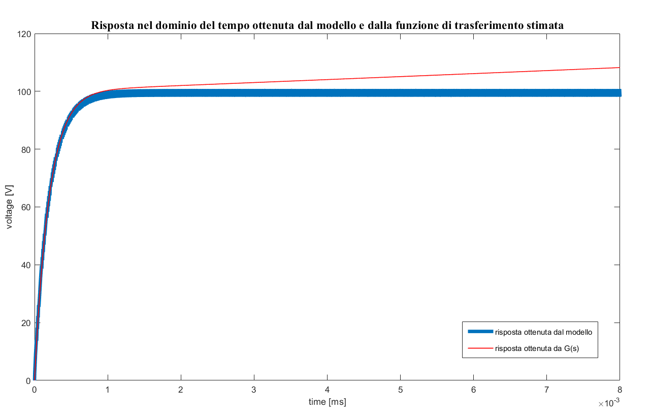
Hi everyone, I'm trying to estimate the Frequency Response of a buck converter. I've found this article: https://it.mathworks.com/company/newsletters/articles/estimating-the-frequency-response-of-a-power-electronics-model.html I've adapted the procedure to a buck converter and followed the instructions but something went wrong. In the last step I've performed a time-domain verification in a Simulink® simulation with the switch-mode buck converter and a Transfer Function block implementing the parametric estimation and compare the response of both systems to the same small perturbation signal but the estimated model response doesn't match the switching model response. I don't know why I've got a diverging systems. I've tried to reduce the load and modify the duty cycle but nothing changed. How can I fix it?
4 Comments
Time DescendingHi, Please, remember that frequency response estimation is the process of extracting/estimating the small-signal behavior of a nonlinear model (in this example it is a switching converter) around a steady-state operating point. This linearized behavior is valid ONLY in the neighborhood of the steady-state operating point. In your time-domain verification you are applying a large-signal perturbation to the duty-cycle (the converter startup), thus violating the above small-signal assumption. In the article, you can read: "We measure and compare the response of both systems to the same small perturbation signal, that is, a 2% positive step superimposed on the steady-state duty cycle." Therefore, you have to make sure that the duty cycle first reaches its steady-state value, and then you can perturb it with e.g. a small-amplitude step. I have modified your model as you can see in the attachment. Hope this helps, Antonino
Thank you so much for your time and patience. I've figured out and understood the mistake,thanks again. I was impressed by the interesting article you and mr Arkadiy Turevskiy wrote. I'm just curious about the ripple voltage that you obtained. In the last figure (figure 8 of the article), the ripple voltage of the switching model response is 10V (from 395 to 405 V). I'd like to know if there is a way to reduce it. Appreciatively, Venia
Dear Venia, I am glad that the article is useful for your work.
As far as the voltage ripple, you can reduce it by increasing the capacitor value. However, this will impact the dynamics of the converter. The power electronics literature is plenty of steady-state and dynamic analyses for fundamental topologies such as buck, boost, and buck-boost converters. In general, power electronics engineers design converter's reactive component values to obtain the desired values for current and voltage ripples, by making sure that the resultant resonant frequency won't be unnecessarily too low with the desired amount of damping. Hope this helps, Antonino
Just in case you want to check this fresh-new technical article out, please go to https://www.mathworks.com/company/newsletters/articles/estimating-the-frequency-response-of-a-power-electronic-model-sinestream-vs-pseudo-random-binary-sequence.html