PMLSM Power Invertor 1st Order Transfer Function
Hi All,
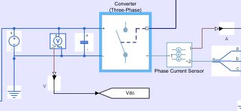
Looking for guidance on how to represent a PMSM 3-Phase Converter (DC bus to AC) as a simply 1st Order Transfer Function in my Simulink model.
Researching this, have found we can show the Power Converter as a simple gain and time delay such as G_inv(s) = K_Inv/(1 + T_inv s)


The gain requires V_cm, which is the control voltage, is this control voltage the "Forward Voltage, Vf" in Switching Devices tab in the block?
Is my assumption for the tf for the converter correct?
Thanks
Patrick
2 Comments
Time DescendingHello Patrick,
you would interface the transfer function in one of two ways. You can either build a custom simscape block to do it, or, more simply, connect a Simulink transfer function to the simscape network with controlled voltage source and sensors. However, the second approach will not draw the correct load current from your simscape network unless you also model that. You could calculate the load current and inject it with a controlled current source. The custom simscape block will be a better solution, but require more work to get working.
An alternative is to use an average converter block, which will speed up simulation. Modelling certain converters as a transfer function usually makes more sense when those converters have capacitors and inductors in them, such as buck and boost converters. For a three phase inverter, there is no actual lag until you take into account motor impedances or filters (I'm ignoring the small capacitances and inductances that are part of a three phase inverter)
The control voltage is not the forward voltage. Forward voltage is device specific and in the order of magnitude of a volt. The control voltage is the actual voltage you will control out of the inverter. Whether is means RMS or not, I cannot say.
Regards,
Joel
Hi Joel,
Many thanks for your reply.
The transfer function approximation of the PWM and Inverter will be used in a "small signal" Simulink model of the PMSM and drive, so can simply use a tf block in Simulink once happy with the tf Gain and time constant that best describes the Inverter.
My "Non-Linear" SimScape model will use the Converter block.
Can approximate the time delay of the PWM with the time constant of the 1st order tf.
Approximating the gain, is where finding Vcm is being trouble some.
The text i am referencing to in my research implies V_cm (Maximum Controller Voltage) is DC and either +- 10 or +-5 v, see below screen grab from the text, which is based on an induction motor model. My take is that V_cm is the current controller output to the Inverter rather than the AC phase output from the Invertor, however that could be wrong as this is to calculate the gain of the Inverter?

Any help on what V_cm refers to would be great.
Cheers
Patrick