Wi-Fi 8 Transmitter Measurements
This example shows how to measure transmitter modulation accuracy and spectral mask for IEEE® 802.11bn™ (Wi-Fi® 8) waveforms.
Example Overview
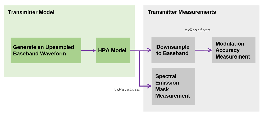
In this example, you generate an oversampled WiFi-8 ultra high reliability (UHR) multi-user (MU) or trigger-based (TB) waveform, as defined in IEEE P802.11bn/D1.0 [1]. You can introduce in-band distortion and spectral regrowth by using a high-power amplifier (HPA) model. You then perform the transmitter modulation accuracy and required spectral mask on the waveform for the measurement configuration specified in Section 38.3.25 of [1].
For each user, the example decodes the UHR-Data field and measures the error vector magnitude (EVM) to determine the modulation accuracy after downsampling the waveform to baseband sampling rate. This diagram shows the example workflow.
Simulation Setup
Configure the example to generate two UHR packets with a 10 microsecond idle period between each packet.
numPackets =2; idleTime =
10;
Waveform Configuration and Generation
This example supports generation of UHR MU and UHR TB packet formats. For more information about the parameterization and generation of IEEE 802.11bn UHR MU and UHR TB waveforms, see the Wi-Fi 8 Waveform Generation example.
rng(0,"twister"); % Set random state pktFormat ="UHR-MU"; % Set the packet format to UHR MU or UHR TB
Configure transmission parameters of an UHR MU packet by using a UHR MU configuration object, uhrMUConfig. For an OFDMA PPDU type, create an OFDMA configuration for a 20 MHz UHR MU packet with allocation index 48 as defined in Table 38-28 of [1]. This allocation has one 106+26-tone multiple resource unit (MRU) and one 106-tone resource unit (RU). This configuration specifies the transmission of a single user per RU. Set the transmission parameters for each user. This example configures the first user to use unequal modulation (UEQM) and the second user to utilize equal modulation (EQM).
if pktFormat=="UHR-MU"
    allocationIndex = 48;                            % Allocation index 48 specifies two RUs ([106+26] [106]) tones and two users
    % First user - 4096 QAM and 1024 QAM (UEQM)
    % Second user - 64 QAM (EQM)
    mcs = {[13 11],7};                               % Modulation and coding scheme (MCS) per user
    spatialMapping = ["Direct" "Direct"];            % Spatial mapping per RU
    apepLength = [1e4 2e4];                          % A-MPDU length pre-EOF padding in bytes per user
    numSTS = [2 2];                                  % Number of space-time streams per user
    channelCoding = ["LDPC" "LDPC2x"];               % Set the channel coding property per user
    numTx = 2;                                       % Number of transmit antennas

    cfgUHR = uhrMUConfig(allocationIndex);
    chanBW = cfgUHR.ChannelBandwidth;
    numUsers = numel(cfgUHR.User);
    cfgUHR.NumTransmitAntennas = numTx;
    for i = 1:numUsers
        cfgUHR.RU{i}.SpatialMapping = spatialMapping(i);
        cfgUHR.User{i}.APEPLength = apepLength(i);
        cfgUHR.User{i}.MCS = mcs{i};
        cfgUHR.User{i}.NumSpaceTimeStreams = numSTS(i);
        cfgUHR.User{i}.ChannelCoding = channelCoding(i);
    end
end
You can also configure this example to generate a single user TB transmission on a DRU. The 26 noncontiguous subcarriers are assigned to a single user in an uplink transmission with a 20 MHz distribution bandwidth (DBW).
if pktFormat=="UHR-TB"
    chanBW = "CBW20";
    mcs = 3;                                         % MCS - 16 QAM
    lsigLength = 4e3;
    numTx = 1;

    numUsers = 1;
    cfgUHR = uhrTBConfig(ChannelBandwidth=chanBW);
    cfgUHR.NumTransmitAntennas = numTx;
    cfgUHR.NumSpaceTimeStreams = numTx;
    cfgUHR.RUSize = 26;
    cfgUHR.RUIndex = 1;
    cfgUHR.LSIGLength = lsigLength;
    cfgUHR.MCS = mcs;
    cfgUHR.DRU = true;
    cfgUHR.DistributionBandwidth = "DBW20";
end
To model the effect of an HPA on the waveform and view the out-of-band spectral emissions, you must oversample the waveform. Generate an oversampled waveform by using a larger IFFT than required for the nominal baseband rate.
osf =4; % Oversampling factor
Create random bits for all packets.
psduLen = psduLength(cfgUHR).*8;
data = cell(1,numUsers);
for i=1:numUsers
    data{i} = randi([0 1],psduLen(i)*numPackets,1);
end
Generate the UHR waveform for the specified bits and configuration by using the uhrWaveformGenerator function. Specify the desired oversampling factor, number of packets, and idle time between each packet.
txWaveform = uhrWaveformGenerator(data,cfgUHR, ...
    NumPackets=numPackets, ...
    IdleTime=idleTime*1e-6, ...
    OversamplingFactor=osf);
Get the baseband sampling rate of the waveform.
fs = wlanSampleRate(chanBW);
disp("Baseband sampling rate: "+(fs/1e6)+" Msps");
Baseband sampling rate: 20 Msps
Prepend zeros to the waveform to allow for early timing synchronization.
txWaveform = [zeros(round(idleTime*1e-6*fs),numTx); txWaveform];
Addition of Impairments
HPA Modeling
The HPA introduces nonlinear behavior in the form of in-band distortion and spectral regrowth. This example simulates the power amplifiers by using the Rapp model [2], which introduces AM/AM distortion.
Model the amplifier by using the comm.MemorylessNonlinearity object and configure reduced distortion by specifying a backoff, hpaBackoff, such that the amplifier operates below its saturation point. You can increase the backoff to reduce EVM for higher MCS values.
pSaturation = 25;                            % Saturation power of a power amplifier in dBm
hpaBackoff = 16;                             % Power amplifier backoff in dB
nonLinearity = comm.MemorylessNonlinearity;
nonLinearity.Method = "Rapp model";
nonLinearity.Smoothness = 3;                 % p parameter
nonLinearity.LinearGain = -hpaBackoff;
nonLinearity.OutputSaturationLevel = db2mag(pSaturation-30);
txWaveform = nonLinearity(txWaveform);
Thermal Noise
Add thermal noise to each transmit antenna by using the comm.ThermalNoise object with a noise figure of 6 dB [3].
thNoise = comm.ThermalNoise(NoiseMethod="Noise Figure",SampleRate=fs*osf,NoiseFigure=6);
txWaveform = thNoise(txWaveform);
Downsampling and Filtering
Resample the oversampled waveform down to baseband for physical layer processing and EVM measurements, applying a low-pass anti-aliasing filter before downsampling. The impact of the low-pass filter is visible in the EVM measurement. Set the parameters for the anti-aliasing filter so that all active subcarriers are within the filter passband.
Design the resampling filter.
aStop = 40; % Stopband attenuation
ofdmInfo = uhrOFDMInfo("UHR-Data",cfgUHR,1);            % OFDM parameters for the first RU
SCS = fs/ofdmInfo.FFTLength;                            % Subcarrier spacing
txbw = max(abs(ofdmInfo.ActiveFrequencyIndices))*2*SCS; % Occupied bandwidth
[L,M] = rat(1/osf);
maxLM = max([L M]);
R = (fs-txbw)/fs;
TW = 2*R/maxLM;                                         % Transition width
Resample the waveform to baseband.
firdec = designMultirateFIR(L,M,TW,aStop,SystemObject=true);
rxWaveform = firdec(txWaveform);
Receiver Processing
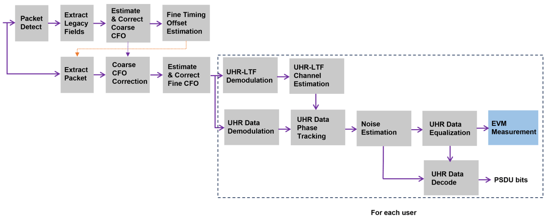
In this section, you detect, synchronize, and extract each packet in rxWaveform, and then measure the EVM. For each packet, perform these steps:
Detect the start of the packet.
Extract the legacy fields.
Estimate and correct coarse carrier frequency offset (CFO).
Perform fine symbol timing estimate by using the frequency-corrected legacy fields.
Extract the packet from the waveform by using the fine symbol timing offset.
Correct the extracted packet with the coarse CFO estimate.
Extract the legacy-long training field (L-LTF), then estimate and correct the fine CFO.
For each packet and each user, perform these steps:
Extract the UHR-LTF and perform channel estimation for each of the transmit streams.
Extract and OFDM-demodulate the UHR-Data field.
Perform noise estimation by using the demodulated data field pilots and single-stream channel estimate at pilot subcarriers.
Phase-correct and equalize the UHR-Data field by using the channel and noise estimates.
For each data-carrying subcarrier in each spatial stream, find the closest constellation point and measure the EVM.
Recover the PSDU by decoding the equalized symbols.
This diagram shows the processing chain.
This example performs two different EVM measurements.
RMS EVM per user per packet, which comprises averaging the EVM over subcarriers, OFDM symbols, and spatial streams.
RMS EVM per subcarrier per spatial stream per user for a packet. Because this configuration maps spatial streams directly to antennas, this measurement can help detect frequency-dependent impairments, which tend to affect individual RF chains differently. This measurement averages the EVM over OFDM symbols only.
Get indices for accessing each field within the time-domain packet.
ind = uhrFieldIndices(cfgUHR);
Define the minimum detectable length of data, in samples.
minPktLen = double(ind.LSTF(2)-ind.LSTF(1))+1;
Detect and process packets within the received waveform by using a while loop, which performs these steps:
Detect a packet by indexing into
rxWaveformwith the sample offset,searchOffset.Detect and process the first packet within
rxWaveform.Detect and process the next packet by incrementing the sample index offset.
Repeat until no further packets are detected.
rxWaveformLength = size(rxWaveform,1);
pktLength = double(ind.UHRData(2));
rmsEVM = zeros(numPackets,numUsers);
eqSym = cell(1,numUsers);
evmPerSC = cell(1,numUsers);
decodeSuccess = false(numPackets,numUsers);
passSF = false(numPackets,1);
pktOffsetStore = zeros(numPackets,1);
iqImbalEst = [0 0];

pktNum = 0;
searchOffset = 0; % Start at first sample (no offset)
while (searchOffset+minPktLen)<=rxWaveformLength

    % Detect packet and determine coarse packet offset
    pktOffset = wlanPacketDetect(rxWaveform,cfgUHR.ChannelBandwidth,searchOffset);
    % Packet offset from start of the waveform
    pktOffset = searchOffset+pktOffset;
    % Skip packet if legacy-short training field (L-STF) is empty
    if isempty(pktOffset) || (pktOffset<0) || ...
            ((pktOffset+ind.LSIG(2))>rxWaveformLength)
        break;
    end

    % Extract L-STF and perform coarse frequency offset correction
    nonht = rxWaveform(pktOffset+(ind.LSTF(1):ind.LSIG(2)),:);
    coarsefreqOff = wlanCoarseCFOEstimate(nonht,cfgUHR.ChannelBandwidth);
    nonht = frequencyOffset(nonht,fs,-coarsefreqOff);

    % Extract the legacy fields and determine fine packet offset
    lltfOffset = wlanSymbolTimingEstimate(nonht,cfgUHR.ChannelBandwidth);
    pktOffset = pktOffset+lltfOffset; % Determine packet offset

    % If offset is outside the bounds of the waveform, then skip samples
    % and continue searching within remainder of the waveform
    if (pktOffset<0) || ((pktOffset+pktLength)>rxWaveformLength)
        searchOffset = pktOffset+double(ind.LSTF(2))+1;
        continue;
    end

    % Timing synchronization complete; extract the detected packet
    rxPacket = rxWaveform(pktOffset+(1:pktLength),:);
    pktNum = pktNum+1;

    % Apply coarse frequency correction to the extracted packet
    rxPacket = frequencyOffset(rxPacket,fs,-coarsefreqOff);

    % Perform fine frequency offset correction on the extracted packet
    lltf = rxPacket(ind.LLTF(1):ind.LLTF(2),:); % Extract L-LTF
    fineFreqOff = wlanFineCFOEstimate(lltf,cfgUHR.ChannelBandwidth);
    rxPacket = frequencyOffset(rxPacket,fs,-fineFreqOff);

    % Extract UHR-LTF samples, demodulate, and perform channel estimation
    uhrLTF = rxPacket(ind.UHRLTF(1):ind.UHRLTF(2),:);
    for i = 1:numUsers
        uhrLTFDemod = uhrDemodulate(uhrLTF,"UHR-LTF",cfgUHR,i);

        % Estimate channel
        [chanEst,pilotEst] = uhrLTFChannelEstimate(uhrLTFDemod,cfgUHR,i);

        % Data demodulate
        rxData = rxPacket(ind.UHRData(1):ind.UHRData(2),:);
        demodSym = uhrDemodulate(rxData,"UHR-Data",cfgUHR,i);

        % Perform pilot phase tracking
        demodSym = uhrTrackPilotError(demodSym,chanEst,cfgUHR,"UHR-Data",i);

        % Estimate noise power in UHR fields
        ofdmInfo = uhrOFDMInfo("UHR-Data",cfgUHR,i); % OFDM parameters
        nVarEst = uhrDataNoiseEstimate(demodSym(ofdmInfo.PilotIndices,:,:),pilotEst,cfgUHR,i);

        % Extract data subcarriers from demodulated symbols and channel
        % estimate
        demodDataSym = demodSym(ofdmInfo.DataIndices,:,:);
        chanEstData = chanEst(ofdmInfo.DataIndices,:,:);

        % Equalize
        [eqSym{i},csi] = uhrEqualize(demodDataSym,chanEstData,nVarEst,cfgUHR,"UHR-Data",i);

        % Set up EVM measurements
        [EVMPerPkt,EVMPerSC] = evmSetup(cfgUHR,i);

        % Compute RMS EVM over all spatial streams for the packet
        rmsEVM(pktNum,i) = EVMPerPkt(eqSym{i});

        % Compute RMS EVM per subcarrier and spatial stream for the packet
        evmPerSC{i} = EVMPerSC(eqSym{i}); % Nst-by-1-by-Nss

        % Recover data field bits
        rxPSDU = uhrDataBitRecover(eqSym{i},nVarEst,csi,cfgUHR,i,EarlyTermination=true);

        if isequal(rxPSDU,data{i}((1:psduLen(i))+(pktNum-1)*psduLen(i)))
            decodeSuccess(pktNum,i) = true;
        end
    end

    % 1st Plot: equalized constellation per packet per spatial stream per user
    % 2nd Plot: RMS EVM per subcarrier per packet per spatial stream per user
    ehtTxEVMConstellationPlots(eqSym,evmPerSC,cfgUHR,pktNum);

    % Store the offset of each packet within the waveform
    pktOffsetStore(pktNum) = pktOffset;

    % Increment waveform offset and search remaining waveform for a packet
    searchOffset = pktOffset+pktLength+minPktLen;
end
![]()
![]()
![]()
![]()
EVM Measurement
Set the unit of EVM to decibel or percentage.
evmUnit =  "Decibel";
Display tables for decode status and measurement summary. The Packet EVM column of the Measurement Summary table displays the average EVM for all users in a packet.
ehtMeasurementSummary(cfgUHR,rmsEVM,decodeSuccess,pktOffsetStore,passSF,evmUnit,false,iqImbalEst);
Decode Status

    Packet Number    Start Index     User 1       User 2
    _____________    ___________    _________    _________

          1                74       "Success"    "Success"
          2             52194       "Success"    "Success"

Measurement Summary

    Packet Number    User 1 EVM (dB)    User 2 EVM (dB)    Packet EVM (dB)
    _____________    _______________    _______________    _______________

          1              -56.693            -56.017            -56.349
          2              -56.316            -56.136            -56.226

Average EVM for 2 users:
  User 1: -56.50dB
  User 2: -56.08dB
  All users: -56.29dB
Spectral Mask Measurement
In this section, you measure the spectral mask of the filtered and impaired waveform after HPA modeling. The transmitter spectral mask test [4] uses a time-gated spectral measurement of the UHR Data field. The example extracts the UHR Data field of each packet from the oversampled waveform by using the start indices of each packet within the baseband waveform. Any delay introduced in the baseband processing chain used to determine the packet indices must be accounted for when gating the UHR Data field within txWaveform. Concatenate the extracted UHR Data fields in preparation for measurement.
startIdx = osf*(ind.UHRData(1)-1)+1; % Upsampled start of UHR Data
endIdx = osf*ind.UHRData(2);         % Upsampled end of UHR Data
delay = grpdelay(firdec,1);          % Group delay of downsampling filter
numPackets = pktNum;
idx = zeros(endIdx-startIdx+1,numPackets);
for pktIdx = 1:numPackets
    % Start of packet in txWaveform
    pktOffset = round(osf*pktOffsetStore(pktIdx))-delay;
    % Indices of UHR Data in txWaveform
    idx(:,pktIdx) = (pktOffset+(startIdx:endIdx));
end
gatedUHRData = txWaveform(idx(:),:);
if numPackets>0
    ehtSpectralMaskTest(gatedUHRData,fs,osf);
end
Spectral mask passed
![]()
![]()
Summary and Further Exploration
This example shows how to measure and plot these properties of a Wi-Fi 8 waveform.
RMS EVM per subcarrier
Equalized constellation
Spectral mask
The HPA model introduces significant in-band distortion and spectral regrowth, which is visible in the EVM results, noisy constellation, and out-of-band emissions in the spectral mask plot. Try increasing the HPA backoff and observe the improved EVM, constellation, and lower out-of-band emissions. The downsampling (to bring the waveform to baseband for processing) stage includes filtering. Try using a different filter or changing the stop-band attenuation and observe the impact on the EVM and constellation.
References
[1] IEEE P802.11bn/D1.0, Aug 2025. IEEE Standard for Information Technology - Telecommunications and Information Exchange between Systems - Local and Metropolitan Area Networks - Specific Requirements - Part 11: Wireless LAN Medium Access Control (MAC) and Physical Layer (PHY) Specifications - Amendment 6: Enhancements for ultra-high reliability (UHR).
[2] Loc and Cheong. IEEE P802.11 Wireless LANs. TGac Functional Requirements and Evaluation Methodology Rev. 16. 2011-01-19.
[3] Perahia, Eldad, and Robert Stacey. Next Generation Wireless LANs: 802.11n, 802.11ac, and Wi-Fi Direct. Second edition, Cambridge University Press, 2013.
[4] Archambault, Jerry, and Shravan Surineni. IEEE 802.11 spectral measurements using vector signal analyzers. RF Design 27.6 (2004): 38–49.