802.11ad Transmitter Spectral Emission Mask Testing
This example shows how to perform pulse shaping and spectrum emission mask testing on an IEEE® 802.11ad™ waveform.
Introduction
IEEE 802.11ad [ 1 ] standard, commonly referred to as directional multi-gigabit (DMG), provides data throughput up to 7 Gbps using the 60 GHz industrial, scientific, and medical (ISM) frequency band. The DMG standard supports three PHY types:
A Control PHY using MCS 0
A Single Carrier (SC) PHY using MCS 1 to MCS 12 and low power SC PHY using MCS 25 to MCS 32
An OFDM PHY using MCS 13 to MCS 24.
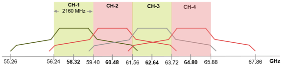
DMG defines four 2.16 GHz wide operating channels, typically in the 57-66 GHz band. The spectral mask test, as demonstrated in this example, ensures a transmission in one channel does not cause substantial interference in adjacent channels. The DMG channelization is shown in the figure below.
The SC DMG PHY uses single-carrier (SC) modulation for low cost, short range applications. This example shows how pulse shaping and spectrum mask measurements can be performed on an SC DMG modulated waveform. The waveform is generated using WLAN Toolbox™, but a waveform captured with a spectrum analyzer could also be used. The transmitter spectrum mask and required spectral flatness for DMG configuration is specified in IEEE 802.11ad [ 1 ], Section 20.3.2.
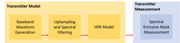
This example generates five DMG SC packets, each separated by a one microsecond gap. Random data is used in each packet and pi/2-16QAM modulation is used. To meet the spectral mask requirements, the baseband waveform is upsampled and filtered to reduce the out-of-band emissions. A high power amplifier (HPA) model is used to introduce inband distortion and spectral regrowth. The spectral emission mask measurement is performed on the upsampled waveform after the HPA modeling. The test schematic is illustrated in the following diagram:
DMG, Single Carrier Packet Configuration
In this example, an IEEE 802.11ad waveform consisting of multiple DMG SC packets is generated. The DMG SC waveform properties are specified in a wlanDMGConfig configuration object. The object is configured for an MCS index of 5, with no TrainingLength fields appended to the packets. Per the test requirement (specified in IEEE 802.11ad Section 21.3.2), the PSDULength is set to 20000 for the packet to ensure that the transmit spectral mask is measured on a DMG packet longer than 10 microseconds.
cfgDMG = wlanDMGConfig;    % DMG packet configuration
cfgDMG.MCS = 5;            % SC PHY with pi/2-BPSK modulation
cfgDMG.PSDULength = 20000; % Length in Bytes
Baseband Waveform Generation
The waveform generator can be configured to generate one or more packets with idle time between each packet. In this example, wlanWaveformGenerator is configured to generate five packets filled with random payload data. Each packet is separated by a one microsecond idle period in between and a random scrambler seed is used to generate each packet.
% Set random stream for repeatability of results
s = rng(98765);

% Generate a multi-packet waveform
idleTime = 1e-6; % One microsecond idle time between packets
numPackets = 5;  % Generate five packets

% Create random bits for all payload data; PSDULength is in bytes
psdu = randi([0 1],cfgDMG.PSDULength*8*numPackets,1);

% Override the ScramblerInitialization property of the DMG configuration
% object by specifying the scrambler initialization
genWaveform = wlanWaveformGenerator(psdu,cfgDMG,...
    'IdleTime',idleTime, ...
    'NumPackets',numPackets, ...
    'ScramblerInitialization',randi([1 127],numPackets,1));

% Get the sampling rate of the waveform
fs = wlanSampleRate(cfgDMG);
disp(['Baseband sampling rate: ' num2str(fs/1e6) ' Msps']);
Baseband sampling rate: 1760 Msps
Oversampling and Filtering
Spectral filtering is used to reduce the out-of-band spectral emissions due to the spread spectrum characteristics of the transmitted waveform and spectral regrowth caused by the HPA in an RF chain. The waveform must be oversampled to model the effect of the HPA on the waveform and view the out-of-band spectral emissions. In this example, the waveform is oversampled and filtered through a raised cosine filter using comm.RaisedCosineTransmitFilter. To meet the spectral mask requirements, the raised cosine filter is truncated to the duration of eight symbols and the roll-off factor is set to 0.5.
% Define the pulse shaping filter characteristics
Nsym = 8;   % Filter span in symbol durations
beta = 0.5; % Roll-off factor
osps = 4;   % Output samples per symbol

% Create raised cosine transmit filter system object
rcosFlt = comm.RaisedCosineTransmitFilter(...
    'Shape','Normal', ...
    'RolloffFactor',beta, ...
    'FilterSpanInSymbols',Nsym, ...
    'OutputSamplesPerSymbol',osps);

% Filter transmit signal for pulse shaping
filterWaveform = rcosFlt([genWaveform; zeros(Nsym/2,1)]);

% Plot the magnitude and phase response of the pulse shaping filter
filterAnalyzer(rcosFlt,OverlayAnalysis="phase",SampleRates=osps*fs)

High Power Amplifier Modeling
Within an RF chain, the HPA is a necessary component but it introduces nonlinear behavior in the form of inband distortion and spectral regrowth. The Rapp model, described in [ 2 ], can be used to model an 802.11ad power amplifier. The Rapp model causes AM/AM distortion and is modeled with comm.MemorylessNonlinearity. The HPA is backed-off to operate below the saturation point to reduce distortion.
hpaBackoff = 0.5; % Power Amplifier backoff in dB

% Create and configure a memoryless nonlinearity to model HPA
nonLinearity = comm.MemorylessNonlinearity;
nonLinearity.Method = 'Rapp model';
nonLinearity.Smoothness = 0.81;                        % Smoothness factor
nonLinearity.LinearGain = 20*log10(4.65) - hpaBackoff; % Small signal gain
nonLinearity.OutputSaturationLevel = 0.58;             % Saturation level

% Apply the model
txWaveform = nonLinearity(filterWaveform);
Transmit Spectrum Emission Mask Measurement
IEEE 802.11ad [ 1 ], Section 20.3.2, specifies the transmit spectral mask that all DMG waveforms must adhere to and describes the packet characteristics. According to the test definition, packets should have no training fields appended and be greater than 10 microseconds in duration.
dBrLimits = [-30 -30 -22 -17 0 0 -17 -22 -30 -30];
fLimits = [-Inf -3.06 -2.7 -1.2 -0.94 0.94 1.2 2.7 3.06 Inf] * 1e3;
rbw = 1e6; % Resolution bandwidth in Hz
vbw = 300e3; % Video bandwidth in Hz
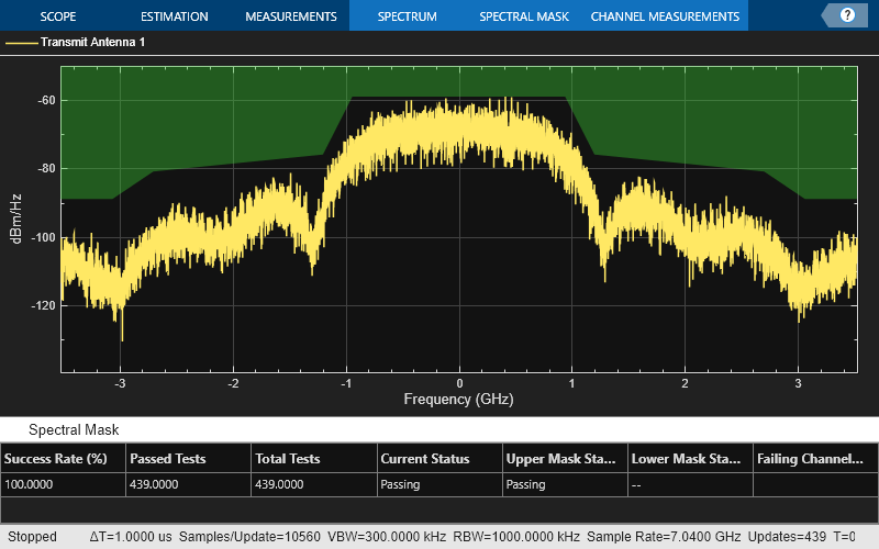
Use the helper function helperSpectralMaskTest to generate a plot that overlays the required spectral mask with the measured PSD. It checks the transmitted PSD levels to be within the specified mask levels and displays a pass/fail status after the test.
helperSpectralMaskTest(txWaveform,fs,osps,dBrLimits,fLimits,rbw,vbw);

% Restore default stream
rng(s);
Spectrum mask passed
Conclusion and Further Exploration
The transmit spectral mask for a DMG SC waveform in the 60 GHz band for a 2.16 GHz channel bandwidth is shown in this example. It also illustrates that the spectrum of the transmitted signal satisfies regulatory restrictions by falling within the spectral mask after pulse shaping. A similar result can be generated for DMG Control and OFDM PHYs.
The HPA model and the spectral filtering affect the out-of-band emissions in the spectral mask plot. For Single Carrier and Control PHY, you can try using different pulse shaping filter parameters and/or decrease or increase the smoothness factor.
For information on other transmitter measurements like modulation accuracy and spectral flatness, refer to the following examples:
Selected Bibliography
IEEE Std 802.11™-2020. IEEE Standard for Information Technology - Telecommunications and Information Exchange between Systems - Local and Metropolitan Area Networks - Specific Requirements - Part 11: Wireless LAN Medium Access Control (MAC) and Physical Layer (PHY) Specifications.
Eldad Perahia, et. al. TGad Evaluation Methodology, IEEE 802.11-09/0296r16