WLAN Channel Models
R2026bThis example demonstrates passing WLAN S1G, VHT, HT, and non-HT format waveforms through appropriate fading channel models. When simulating a WLAN communications link, viable options for channel modeling include the TGah,TGn and TGac models from WLAN Toolbox™ and the additive white Gaussian noise (AWGN) and 802.11g models from Communications Toolbox™. In this example, it is sufficient to set the channel model sampling frequency to match the channel bandwidth because no front-end filtering is applied to the signal and the oversampling rate is 1.
In each section of this example, you:
Create a waveform.
Transmit it through a fading channel with noise added.
Use a spectrum analyzer to display the waveform before and after it passes through the noisy fading channel.
Pass S1G Waveform Through TGah SISO Channel
Create a bit stream to use when generating the WLAN S1G format waveform.
bits = randi([0 1],1000,1);
Create an S1G configuration object, and then generate a 2 MHz S1G waveform.
s1g = wlanS1GConfig(APEPLength=1000);
preChS1G = wlanWaveformGenerator(bits,s1g);
Pass the signal through a TGah SISO channel with AWGN noise (SNR = 10 dB) and a receiver with a 9 dB noise figure. Recall that the channel model sampling frequency is equal to the bandwidth in this example. Set property values by using name-value pairs.
Create a TGah channel object. Set the channel model sampling frequency and channel bandwidth, enable path loss and shadowing, and use the Model-D delay profile.
cbw = s1g.ChannelBandwidth;
fs = 2e6; % Channel model sampling frequency equals the channel bandwidth
tgahChan = wlanTGahChannel('SampleRate',fs,'ChannelBandwidth',cbw, ...
    'LargeScaleFadingEffect','Pathloss and shadowing', ...
    'NormalizeChannelOutputs',false, ...
    'DelayProfile','Model-D');
Determine the signal power in dBW, accounting for the TGah large scale fading pathloss. Add AWGN. Account for noise energy in nulls so the SNR is defined per active subcarrier.
snrValue = 10;
ofdmInfo = wlanS1GOFDMInfo('S1G-Data',s1g);
snrdB = convertSNR(snrValue,"snrsc","snr",FFTLength=ofdmInfo.FFTLength,NumActiveSubcarriers=ofdmInfo.NumTones);
sigPowdBW = 10*log10(mean(abs(preChS1G).^2)) - tgahChan.info.Pathloss;
postChS1G = awgn(tgahChan(preChS1G),snrdB,sigPowdBW);
Pass the S1G waveform through the receiver. Add thermal noise at the receiver with a 9 dB noise figure. The noise power is kTBF, where k is Boltzmann's constant, T is the ambient temperature of 290 K, B is the bandwidth, and F is the noise figure.
thNoise = comm.ThermalNoise('NoiseMethod','Noise figure', ...
    'NoiseFigure',9,'SampleRate',fs,'Add290KAntennaNoise',true);
rxS1G = thNoise(postChS1G);
Display a spectrum analyzer with before-channel and after-channel waveforms.
title = '2 MHz S1G Waveform Before and After TGah Channel';
saScope = spectrumAnalyzer(SampleRate=fs,ShowLegend=true,...
    AveragingMethod='exponential',ForgettingFactor=0.99,Title=title,...
    ChannelNames={'Before','After'});
saScope([preChS1G,rxS1G])
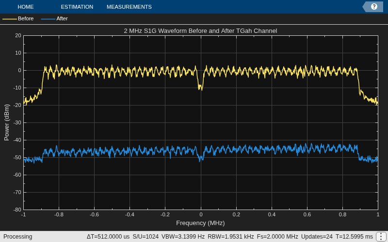
Path loss accounts for the roughly 50 dB of separation between the waveform before and after it passes through the TGah channel. The path loss results from the default transmitter-to-receiver distance of 3 meters, and from shadowing effects. The signal level variation shows the frequency selectivity of the delay profile across the frequency spectrum.
Pass VHT Waveform Through TGac SISO Channel
Create a bit stream to use when generating the WLAN VHT format waveform.
bits = randi([0 1],1000,1);
Create a VHT configuration object, and generate an 80 MHz VHT waveform.
vht = wlanVHTConfig;
preChVHT = wlanWaveformGenerator(bits,vht);
Pass the signal through a TGac SISO channel with AWGN noise (SNR = 10 dB) and a receiver with a 9 dB noise figure. Recall that the channel model sampling frequency is equal to the bandwidth in this example. Set parameters using name-value pairs.
Create a TGac channel object. Set the channel model sampling frequency and channel bandwidth, enable path loss and shadowing, and use the Model-D delay profile.
cbw = vht.ChannelBandwidth;
fs = 80e6; % Channel model sampling frequency equals the channel bandwidth
tgacChan = wlanTGacChannel('SampleRate',fs,'ChannelBandwidth',cbw, ...
    'LargeScaleFadingEffect','Pathloss and shadowing', ...
    'NormalizeChannelOutputs',false, ...
    'DelayProfile','Model-D');
Determine the signal power in dBW, accounting for the TGac large scale fading pathloss. Add AWGN. Account for noise energy in nulls so the SNR is defined per active subcarrier.
snrValue = 10;
ofdmInfo = wlanVHTOFDMInfo('VHT-Data',vht);
snrdB = convertSNR(snrValue,"snrsc","snr",FFTLength=ofdmInfo.FFTLength,NumActiveSubcarriers=ofdmInfo.NumTones);
sigPowdBW = 10*log10(mean(abs(preChVHT).^2)) - tgacChan.info.Pathloss;
postChVHT = awgn(tgacChan(preChVHT),snrdB,sigPowdBW);
Pass the VHT waveform through the receiver. Add thermal noise at the receiver with a 9 dB noise figure. The noise power is kTBF, where k is Boltzmann's constant, T is the ambient temperature of 290 K, B is the bandwidth, and F is the noise figure.
thNoise = comm.ThermalNoise('NoiseMethod','Noise figure', ...
    'NoiseFigure',9,'SampleRate',fs,'Add290KAntennaNoise',true);
rxVHT = thNoise(postChVHT);
Display a spectrum analyzer with before-channel and after-channel waveforms.
title = '80 MHz VHT Waveform Before and After TGac Channel';
saScope = spectrumAnalyzer(SampleRate=fs,ShowLegend=true,...
    AveragingMethod='exponential',ForgettingFactor=0.99,Title=title,...
    ChannelNames={'Before','After'});
saScope([preChVHT,rxVHT])
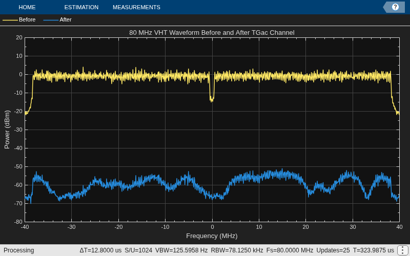
Path loss accounts for the roughly 50 to 60 dB of separation between the waveform before and after it passes through the TGac channel. The path loss results from the default transmitter-to-receiver distance of 3 meters, and from shadowing effects. The signal level variation shows the frequency selectivity of the delay profile across the frequency spectrum.
Pass HT Waveform Through TGn SISO Channel
Create a bit stream to use when generating the WLAN HT format waveform.
bits = randi([0 1],1000,1);
Create an HT configuration object, and generate an HT waveform.
ht = wlanHTConfig;
preChHT = wlanWaveformGenerator(bits,ht);
Pass the signal through a TGn SISO channel with AWGN noise (SNR = 10 dB) and a receiver with a 9 dB noise figure. Recall that the channel model sampling frequency is equal to the bandwidth in this example. Set parameters using name-value pairs.
Create a TGn channel object. Set the channel model sampling frequency and channel bandwidth, enable path loss and shadowing, and use the Model-F delay profile.
fs = 20e6; % Channel model sampling frequency equals the channel bandwidth
tgnChan = wlanTGnChannel('SampleRate',fs,'LargeScaleFadingEffect', ...
    'Pathloss and shadowing','NormalizeChannelOutputs',false, ...
    'DelayProfile','Model-F');
Pass the HT waveform through a TGn channel. Add AWGN. Account for noise energy in nulls so the SNR is defined per active subcarrier.
snrValue = 10;
ofdmInfo = wlanHTOFDMInfo('HT-Data',ht);
snrdB = convertSNR(snrValue,"snrsc","snr",FFTLength=ofdmInfo.FFTLength,NumActiveSubcarriers=ofdmInfo.NumTones);
sigPowdBW = 10*log10(mean(abs(preChHT).^2)) - tgnChan.info.Pathloss;
postChHT = awgn(tgnChan(preChHT),snrdB,sigPowdBW);
Add thermal noise at the receiver with a 9 dB noise figure. The noise power is kTBF, where k is Boltzmann's constant, T is the ambient temperature of 290 K, B is the bandwidth, and F is the noise figure.
thNoise = comm.ThermalNoise('NoiseMethod','Noise figure', ...
    'NoiseFigure',9,'SampleRate',fs,'Add290KAntennaNoise',true);
rxHT = thNoise(postChHT);
Display a spectrum analyzer with before-channel and after-channel waveforms.
title = '20 MHz HT Waveform Before and After TGn Channel';
saScope = spectrumAnalyzer(SampleRate=fs,ShowLegend=true,...
    AveragingMethod='exponential',ForgettingFactor=0.99,Title=title,...
    ChannelNames={'Before','After'});
saScope([preChHT,rxHT])
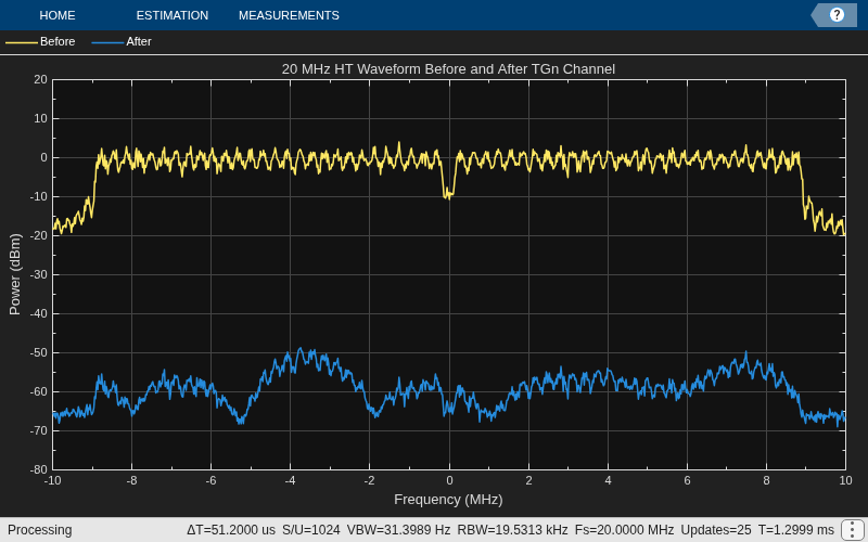
Path loss accounts for the roughly 50 to 60 dB of separation between the waveform before and after it passes through the TGn channel. The path loss results from the default transmitter-to-receiver distance of 3 meters, and from shadowing effects. The signal level variation shows the frequency selectivity of the delay profile across the frequency spectrum.
Pass Non-HT Waveform Through 802.11g Channel
Create a bit stream to use when generating the WLAN Non-HT format waveform.
bits = randi([0 1],1000,1);
Create a non-HT configuration object, and generate a non-HT waveform.
nht = wlanNonHTConfig;
preChNonHT = wlanWaveformGenerator(bits,nht);
Calculate free-space path loss for a transmitter-to-receiver separation distance of 3 meters. Create an 802.11g channel object with a 3 Hz maximum Doppler shift and an RMS path delay equal to two times the sample time. Recall that the channel model sampling frequency is equal to the bandwidth in this example. Create a Rayleigh channel object.
dist = 3;
fc = 2.4e9;
pathLoss = 10^(-log10(4*pi*dist*(fc/3e8)));
fs = 20e6; % Channel model sampling frequency equals the channel bandwidth
maxDoppShift = 3;
trms = 2/fs;
ch802 = comm.RayleighChannel('SampleRate',fs,'MaximumDopplerShift',maxDoppShift, ...
    'NormalizePathGains',false,'PathDelays',trms);
Pass the non-HT waveform through an 802.11g channel. Add AWGN. Account for noise energy in nulls so the SNR is defined per active subcarrier.
snrValue = 10;
ofdmInfo = wlanNonHTOFDMInfo('NonHT-Data');
snrdB = convertSNR(snrValue,"snrsc","snr",FFTLength=ofdmInfo.FFTLength,NumActiveSubcarriers=ofdmInfo.NumTones);
sigPowdBW = 10*log10(mean(abs(preChNonHT).^2));
postChNonHT = awgn(ch802(preChNonHT),snrdB,sigPowdBW);
Apply free-space path loss, then add thermal noise at the receiver with a 9 dB noise figure. The noise power is kTBF, where k is Boltzmann's constant, T is the ambient temperature of 290 K, B is the bandwidth, and F is the noise figure.
thNoise = comm.ThermalNoise('NoiseMethod','Noise figure', ...
    'NoiseFigure',9,'SampleRate',fs,'Add290KAntennaNoise',true);
rxNonHT = thNoise(postChNonHT * pathLoss);
Display a spectrum analyzer with before-channel and after-channel waveforms.
title = '20 MHz Non-HT Waveform Before and After 802.11g Channel';
saScope = spectrumAnalyzer(SampleRate=fs,ShowLegend=true,...
    AveragingMethod='exponential',ForgettingFactor=0.99,Title=title,...
    ChannelNames={'Before','After'});
saScope([preChNonHT,rxNonHT])
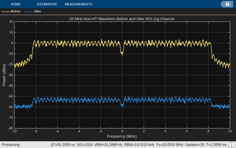
Free-space path loss accounts for the roughly 50 to 60 dB of separation between the waveform before and after it passes through the 802.11g channel. The path loss results from the specified transmitter-to-receiver distance of 3 meters, and from shadowing effects. The signal level variation shows the frequency selectivity of the delay profile across the frequency spectrum.
Pass VHT Waveform Through TGac MIMO Channel
Create a bit stream to use when generating the WLAN VHT format waveform.
bits = randi([0 1],1000,1);
Create a multi-user VHT configuration object, and generate a VHT waveform. Set the number of transmit antennas to four. Set the number of space-time streams and the number of receive antennas to 3. Because the number of transmit antennas is not equal to the number of space-time streams, the spatial mapping is not direct. Set the spatial mapping to Hadamard.
ntx = 4;
nsts = 3;
nrx = 3;
vht = wlanVHTConfig('NumTransmitAntennas',ntx, ...
    'NumSpaceTimeStreams',nsts,'SpatialMapping','Hadamard');
preChVHT = wlanWaveformGenerator(bits,vht);
Create a TGac MIMO channel object. Recall that the channel model sampling frequency is equal to the bandwidth in this example. Disable large-scale fading effects.
cbw = vht.ChannelBandwidth;
fs = 80e6; % Channel model sampling frequency equals the channel bandwidth
tgacChan = wlanTGacChannel('SampleRate',fs,'ChannelBandwidth',cbw,...
    'NumTransmitAntennas',ntx,'NumReceiveAntennas',nrx, ...
    'NormalizeChannelOutputs',false);
tgacChan.LargeScaleFadingEffect = 'None';
Pass the VHT waveform through a TGac channel. Add AWGN. Account for noise energy in nulls so the SNR is defined per active subcarrier.
snrValue = 10;
ofdmInfo = wlanVHTOFDMInfo('VHT-Data',vht);
snrdB = convertSNR(snrValue,"snrsc","snr",FFTLength=ofdmInfo.FFTLength,NumActiveSubcarriers=ofdmInfo.NumTones);
sigPowdBW = 10*log10(sum(mean(abs(preChVHT).^2)));
postChVHT = awgn(tgacChan(preChVHT),snrdB,sigPowdBW);
Add thermal noise at the receiver with a 9 dB noise figure. The noise power is kTBF, where k is Boltzmann's constant, T is the ambient temperature of 290 K, B is the bandwidth, and F is the noise figure.
thNoise = comm.ThermalNoise('NoiseMethod','Noise figure', ...
    'NoiseFigure',9,'SampleRate',fs,'Add290KAntennaNoise',true);
rxVHT = thNoise(postChVHT);
Display a spectrum analyzer showing the multiple streams after the channel effects have been added.
title = '80 MHz VHT 4x3 MIMO Waveform After TGac Channel';
saScope = spectrumAnalyzer(SampleRate=fs,ShowLegend=true,...
    AveragingMethod='exponential',ForgettingFactor=0.99,Title=title,...
    ChannelNames={'RX1','RX2','RX3'});
saScope(rxVHT)
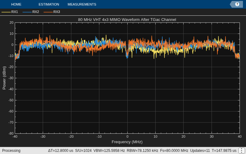
The overlaid signals show the TGac channel variation between the received streams.
References
[1] Erceg, V., L. Schumacher, P. Kyritsi, et al. TGn Channel Models. Version 4. IEEE 802.11-03/940r4, May 2004.
[2] Breit, G., H. Sampath, S. Vermani, et al. TGac Channel Model Addendum. Version 12. IEEE 802.11-09/0308r12, March 2010.
See Also
wlanHTConfig | wlanNonHTConfig | wlanTGacChannel | wlanTGnChannel | wlanTGahChannel | wlanVHTConfig

