Upscale Image by Two
This example shows how to upscale a multicomponent image by a factor of two by using a 5-tap interpolation filter. The algorithm is designed for implementation on FPGAs.
The example uses a 5-tap Gaussian interpolation filter kernel with values [1/8, 1/2, 3/4, 1/2, 1/8]. This kernel has a symmetric structure, which prevents directional bias. Because the division operations are powers of two, they can be implemented with bit-shifts. This kernel gives the largest weight (3/4) to the center coefficient, which preserves the characteristics of the input in the upscaled image.
Map Input and Output Pixels
For each pixel in the input image, P(n), the device-under-test (DUT) generates two output pixels.
Odd-indexed output pixels (Q(1),Q(3),Q(5), ...) are positioned at the locations of the original input pixels. The algorithm calculates these pixel values by using a weighted average of the input pixel at that location and its immediate neighbors.
_Qodd(n) = P(n-1)/8 + 3*P(n)/4 + P(n+1)/8_
Even-indexed output pixels (Q(2), Q(4), Q(6), ...) are additional pixels interpolated between the original input pixels. The algorithm calculates these pixel values by averaging the adjacent input pixels.
_Qeven(n) = P(n)/2 + P(n+1)/2_
This diagram shows the pixel mapping and upscale of a 3-by-4 image into a 6-by-8 image.
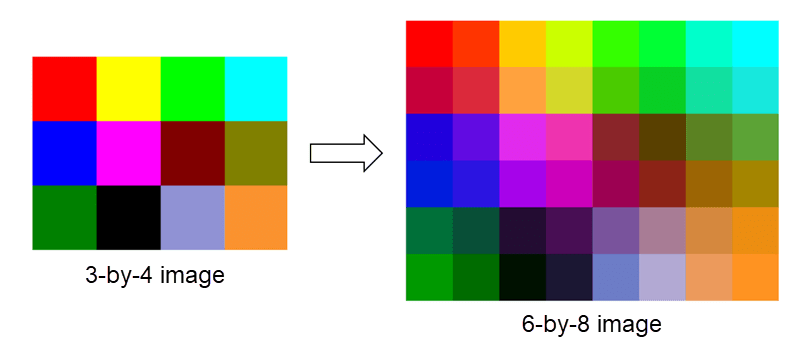
Image Upscale Algorithm
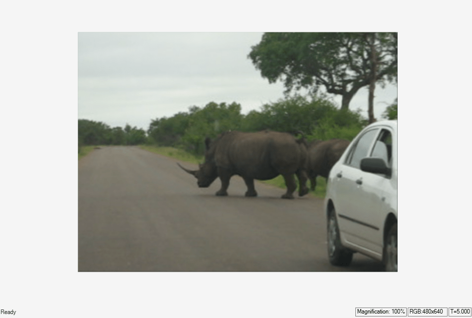
This section describes the example model. The model imports an image file and converts it to pixel-streaming format with accompanying control signals. The model includes Video Viewer blocks that display the input and output images. The model stores and exports the output frame for validation with a MATLAB® script.
open_system("ImageUpscaleX2HDL")
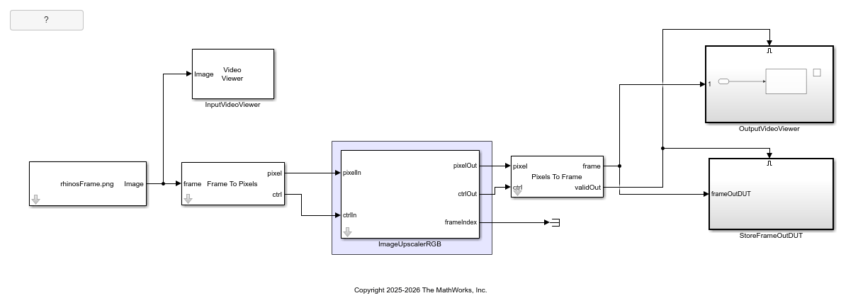
The ImageUpscalerRGB subsystem upsamples the image by adding additional horizontal and vertical lines and calculates the interpolated values in both directions by using the Gaussian kernel. The DUT computes the upscaled image dimensions based on the Input height and Input width parameters. These parameters should match the size of the input from the Source block and the format specified in the Frame to Pixels and Pixels to Frames blocks. The Output horizontal blanking parameter specifies the total inactive cycles between each output line (i.e., frontPorch + backPorch). Specifying blanking smaller than the default for the 480p video format allows better throughput of upscaled frames, but if you set this value smaller than the latency of the filters, the control signals become corrupted. The minimum value for the blanking parameter is 12 cycles. Set the TotalPixelsPerLine parameter of the PixelsToFrame block in the ImageUpscaleX2HDL model to ActivePixelsPerLine + 2*|horizontalBlanking|, where ActivePixelsPerLine is the width of the upscaled (output) image in pixels.
This example upscales a single image input. When you use video source input, use the frameIndex signal to track the correspondence between input and output frames.
open_system("ImageUpscaleX2HDL/ImageUpscalerRGB", "force")
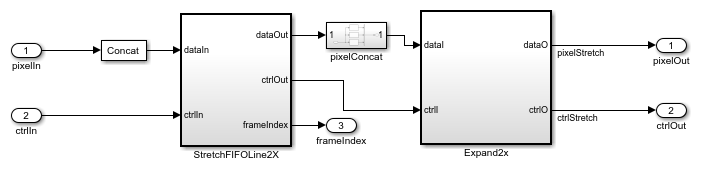
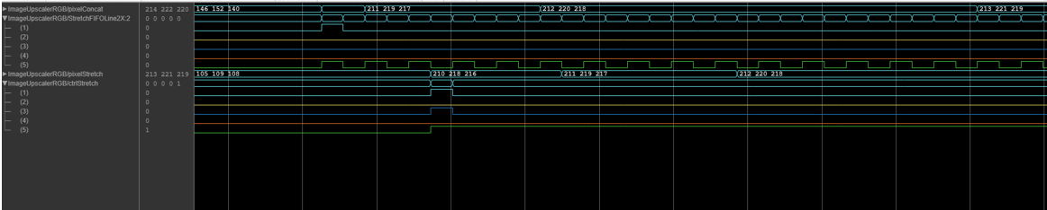
The StretchFIFOLine2X subsystem stretches the horizontal line to accommodate a new interpolated pixel between each two existing pixels. Because the output depends on the neighboring pixels, the DUT contains delay blocks to align the data with control signals. This waveform shows the modified control signals of the stretched input lines.
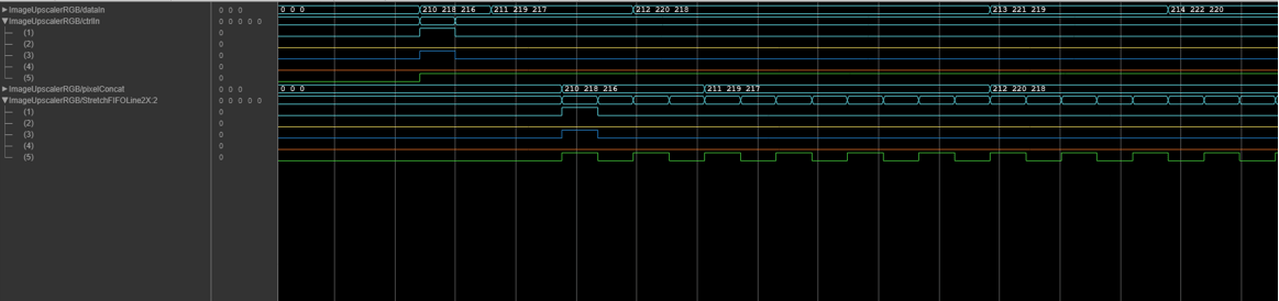
The Expand2X subsystem performs horizontal interpolation followed by vertical interpolation. The UpsampleHorz subsystem filters the stretched image with the 1-by-5 kernel in the horizontal direction. The UpsampleVert subsystem adds lines for the vertically interpolated pixels and filters with the same kernel in the vertical direction. Inside the UpsampleVert subsystem, a dual-port RAM stores the values for the subsequent line while the system reads the current line. This waveform shows the input and output of the Expand2X subsystem.
Because the output frame is four times the size of the input frame, the DUT operates at a lower rate than the input stream. This difference in rates can result in frame loss from the input stream. The DUT does not support control buses with noncontiguous valid signals, multipixel input streams, or images with an odd number of ActivePixelsPerLine or ActiveVideoLines.
Simulate and Verify
Run the simulation to display the upscaled output image. The model exports the output frame from the ImageUpscalerRGB subsystem for validation in MATLAB®.
sim("ImageUpscaleX2HDL")
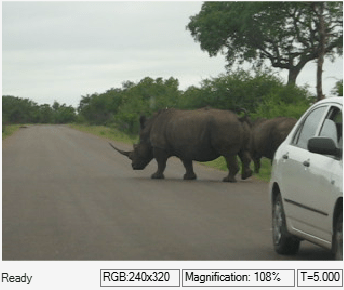
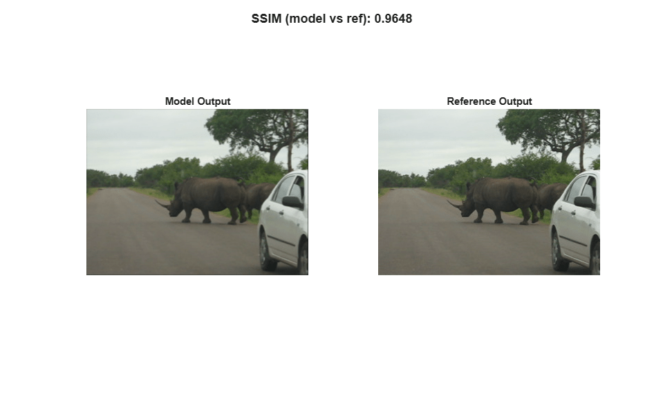
The verifyUpscalex2 script calculates the behavioral reference for the input resolution of 240p and compares it with the simulation output. While this example uses a 240p input, the model has also been validated with input resolutions up to 1080p. Run the script to compare the model output frame with the reference frame.
verifyUpscalex2;
HDL Code Generation
To check and generate the HDL code referenced in this example, you must have an HDL Coder™ license.
To generate the HDL code, use the following command.
makehdl('ImageUpscaleX2HDL/ImageUpscalerRGB')
To generate an HDL test bench, use the following command.
makehdltb('ImageUpscaleX2HDL/ImageUpscalerRGB')
Resource Usage
This table shows the resource usage (in percentage) for the ImageUpscalerRGB subsystem with 240p input in the RGB color space. Each pixel is represented by the uint8 data type. The design was synthesized and put through place and route on an AMD™ Zynq™ ZCU102 Ultrascale+ MpSoC board. The design achieves a clock rate of 348 MHz and uses these resources.
resources = array2table([0.41; 0.16; 0.28; 10.69; 0.24], ...
    'VariableNames', {'Resources'}, ...
    'RowNames', {'LUT', 'LUTRAM', 'FF', 'BRAM', 'DSP'});
disp(resources);
              Resources
              _________

    LUT          0.41
    LUTRAM       0.16
    FF           0.28
    BRAM        10.69
    DSP          0.24