Validate Calibration by Building a Colorized 3-D Map Using MUN-FRL Dataset
R2026bThis example shows how to validate multi-sensor calibration by building a colorized 3-D map from flight data. The workflow fuses lidar, IMU, and camera data using the calibrated parameters, providing an end-to-end check that complements the static projection-based validation. While static validation checks pairwise extrinsics on calibration data, map building uses all parameters under real operating conditions including vibration and rapid motion.
The example loads the lidar trajectory estimated by theFactor Graph-Based Lidar-Inertial Odometry (Point Cloud Toolbox) example and colorizes the lidar map by projecting camera images onto the 3-D point clouds using the calibrated camera-to-lidar extrinsics and camera intrinsics. A crisp, correctly-colored map confirms that the entire calibration pipeline is accurate.
Load Calibration Parameters and Visualize Sensor Configuration
Load the multi-sensor calibration parameters from the multiSensorParameters object produced by the Create Multi-Sensor System from Pairwise Calibrations Using MUN-FRL Dataset example. Plot the sensor mounting configuration to visualize how the sensors are arranged on the platform.
msParams = load("multiSensorMUNFRL.mat").msp;

% Plot the calibrated multi-sensor system
ax = plot(msParams, SensorSize=0.05, FrameSize=0.1, ShowFrameAxisLabels=false);

% Reverse Z-axis to match the IMU body frame convention where Z points down
set(ax, ZDir="reverse");
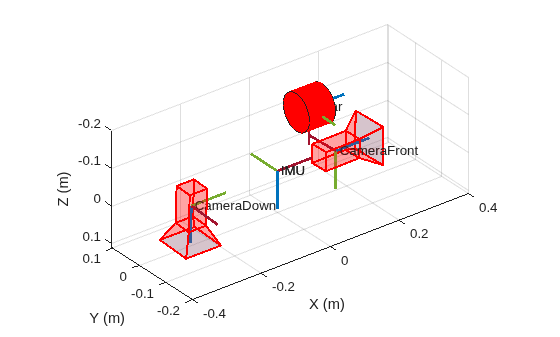
Extract the camera intrinsics, camera-to-lidar extrinsics, and lidar sensor information needed for this workflow.
% Camera intrinsics
intrinsicsDown = intrinsics(msParams, "CameraDown");

% Camera-to-lidar extrinsics
tformCameraToLidar = rigidtform3d(transformation(msParams, "CameraDown", "Lidar"));
Download Multi-Sensor Data
Download the rosbag from the MUN-FRL dataset CCECE 2025 Workshop materials. The rosbag contains synchronized lidar point clouds from a VLP-16 at 10 Hz, down-facing camera images at 20 Hz, and IMU measurements at 400 Hz recorded during a drone flight through an outdoor environment. You can either manually download the data or use the following code to download the file programmatically.
dataFolder = fullfile(tempdir, "MUN-FRL-Lighthouse");
if ~exist(dataFolder, "dir")
    mkdir(dataFolder)
end

bagFile = fullfile(dataFolder, "lighthouse_francis_sample.bag");
if ~exist(bagFile, "file")
    disp("Downloading lighthouse_francis_sample.bag (3.6 GB)...")
    url = "https://drive.usercontent.google.com/download?id=15MovyJSUhj0D2cgWNklvQTru7j6JfUwb&export=download&confirm=t";
    websave(bagFile, url, weboptions(Timeout=Inf));
end
Downloading lighthouse_francis_sample.bag (3.6 GB)...
Load Lidar-Inertial Odometry Results
Load the lidar-inertial odometry results saved by the Factor Graph-Based Lidar-Inertial Odometry (Point Cloud Toolbox) example. The MAT file contains the optimized absolute pose of the lidar at each registered point cloud, the corresponding lidar timestamps, and the frame indices that map each registered view back to the original rosbag message sequence.
To run the full lidar-inertial odometry algorithm, see the Factor Graph-Based Lidar-Inertial Odometry (Point Cloud Toolbox) example. This example loads the results directly.
lioData = load("lioMUNFRL.mat");
lioPoses = rigidtform3d(lioData.lioPoses);
lidarTimesReg = lioData.lidarTimesReg;
frameIndices = lioData.frameIndices;
numViews = numel(lioPoses);
Read Sensor Data from Rosbag
Read lidar and camera messages from the rosbag.
bag = rosbag(bagFile);
% Read lidar messages at the registered frame indices
lidarSel = select(bag, Topic="/velodyne_points");
lidarMsgs = readMessages(lidarSel, DataFormat="struct");

ptClouds = repmat(pointCloud(zeros(1,3)), numViews, 1);
for k = 1:numViews
    msg = lidarMsgs{frameIndices(k)};
    xyz = rosReadXYZ(msg);
    ptClouds(k) = pointCloud(xyz);
end

% Read camera messages
cameraSel = select(bag, Topic="/camera/image_color/compressed");
cameraMsgs = readMessages(cameraSel, DataFormat="struct");

numCam = numel(cameraMsgs);
cameraTimes = zeros(numCam, 1);
for i = 1:numCam
    msg = cameraMsgs{i};
    cameraTimes(i) = double(msg.Header.Stamp.Sec) + double(msg.Header.Stamp.Nsec) * 1e-9;
end
Colorize the Map Using the Down-Facing Camera
For each registered lidar point cloud, find the temporally closest camera image and use fuseCameraToLidar (Point Cloud Toolbox) to color the point cloud. Before projection, use undistortImage to remove the lens distortion using the calibrated camera intrinsics.
% Find closest camera frame for each registered lidar frame
camIdx = interp1(cameraTimes, 1:numCam, lidarTimesReg, "nearest", "extrap");

% Precompute undistortion intrinsics once
[~, newIntrinsics] = undistortImage(zeros(intrinsicsDown.ImageSize(1), ...
    intrinsicsDown.ImageSize(2), 3, "uint8"), intrinsicsDown);

coloredPtClouds = repmat(pointCloud(zeros(1,3)), 1, numViews);
hasColor = false(numViews, 1);

for k = 1:numViews
    ptCloud = ptClouds(k);
    msg = cameraMsgs{camIdx(k)};
    img = rosReadImage(msg, Encoding="rgb8");
    imgUndistorted = undistortImage(img, intrinsicsDown);

    % Colorize this point cloud using undistorted image
    coloredPtCloud = fuseCameraToLidar(imgUndistorted, ptCloud, newIntrinsics, ...
        tformCameraToLidar);

    % Select the points with color
    coloredPtClouds(k) = select(coloredPtCloud, any(coloredPtCloud.Color > 0, 2));
end

% Assemble colorized map
colorizedMap = pcalign(coloredPtClouds, lioPoses);

% Visualize colored point cloud
viewer = pcviewer(colorizedMap);
viewer.CameraZoom = 2.5;
Zoom in on regions with distinct features such as floor markings, wall edges, or structural boundaries, and check for the following indicators.
Point cloud alignment quality validates the lidar-to-IMU extrinsics and IMU noise parameters. When calibration is accurate, consecutive point clouds align precisely and produce sharp edges. Poor lidar-to-IMU calibration causes doubled or blurry edges.
Color consistency validates the camera-to-lidar extrinsics and camera intrinsics. When calibration is accurate, colors align with object boundaries and repeated observations of the same surface have consistent color.
Distortion correction validates the camera intrinsic parameters. When lens distortion parameters are accurate, straight lines in the scene appear straight in the colorized map. Residual barrel or pincushion distortion causes curved color artifacts near the image periphery.
References
[1] Thalagala, Ravindu G., Oscar De Silva, Awantha Jayasiri, Arthur Gubbels, George KI Mann, and Raymond G. Gosine. "MUN-FRL: A visual-inertial-LiDAR dataset for aerial autonomous navigation and mapping." The International Journal of Robotics Research 43, no. 12 (2024): 1853-1866.

