UAV Obstacle Avoidance in Simulink
This model implements waypoint following along with obstacle avoidance on a UAV in a simulated scenario. The model takes a set of waypoints and uses the 3D VFH+ algorithm to provide an obstacle-free path.
Create UAV Scenario with Custom Lidar Sensor and Obstacles
Create Scenario
Create a UAV scenario and set its local origin.
Scenario = uavScenario("UpdateRate",100,"ReferenceLocation",[0 0 0]);
Add a marker to indicate the start pose of the UAV.
addMesh(Scenario,"cylinder",{[0 0 1] [0 .01]},[0 1 0]);Define UAV Platform
Specify the initial position and orientation of the UAV in the north-east-down (NED) frame.
InitialPosition = [0 0 -7];
InitialOrientation = [0 0 0];
Create a UAV platform in the scenario.
platUAV = uavPlatform(UAV=Scenario, ...
                      ReferenceFrame="NED", ...
                      InitialPosition=InitialPosition, ...
                      InitialOrientation=eul2quat(InitialOrientation));
Add a quadrotor mesh for visualization.
updateMesh(platUAV,"quadrotor",{1.2},[0 0 1],eul2tform([0 0 pi]));Create and Mount Sensor Model
Specify the lidar resolution.
AzimuthResolution = 0.5;
ElevationResolution = 2;
Specify the lidar range.
MaxRange = 7;
AzimuthLimits = [-179 179];
ElevationLimits = [-15 15];
Create a statistical sensor model to generate point clouds for the lidar sensor.
LidarModel = uavLidarPointCloudGenerator(UpdateRate=10, ...
                                         MaxRange=MaxRange, ...
                                         RangeAccuracy=3, ...
                                         AzimuthResolution=AzimuthResolution, ...
                                         ElevationResolution=ElevationResolution, ...
                                         AzimuthLimits=AzimuthLimits, ...
                                         ElevationLimits=ElevationLimits, ...
                                         HasOrganizedOutput=true);
Create a lidar sensor and mount the sensor on the quadrotor.
uavSensor("Lidar",platUAV,LidarModel, ...
          MountingLocation=[0 0 -0.4], ...
          MountingAngles=[0 0 180]);
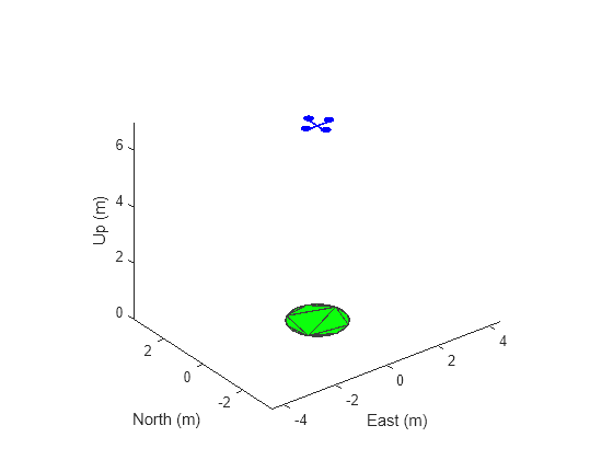
Preview the scenario using the show3D function.
show3D(Scenario);
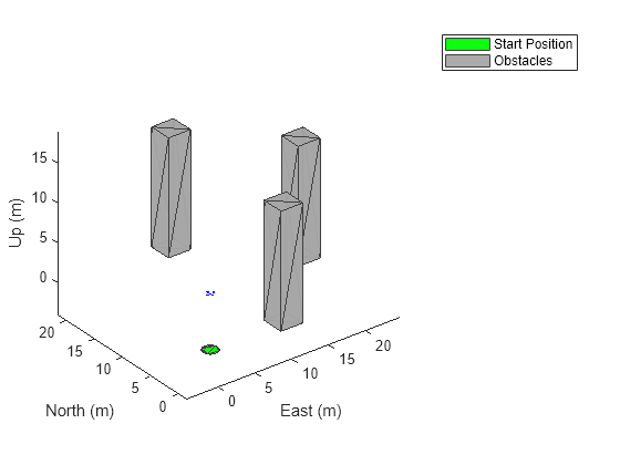
Add Obstacles to Scenario
Add cuboid obstacles, representing buildings, to the scenario.
ObstaclePositions = [10 0; 20 10; 10 20]; % Locations of the obstacles
ObstacleHeight = 15;                      % Height of the obstacles
ObstaclesWidth = 3;                       % Width of the obstacles

for i = 1:size(ObstaclePositions,1)
    addMesh(Scenario,"polygon", ...
        {[ObstaclePositions(i,1)-ObstaclesWidth/2 ObstaclePositions(i,2)-ObstaclesWidth/2; ...
        ObstaclePositions(i,1)+ObstaclesWidth/2 ObstaclePositions(i,2)-ObstaclesWidth/2; ...
        ObstaclePositions(i,1)+ObstaclesWidth/2 ObstaclePositions(i,2)+ObstaclesWidth/2; ...
        ObstaclePositions(i,1)-ObstaclesWidth/2 ObstaclePositions(i,2)+ObstaclesWidth/2], ...
        [0 ObstacleHeight]},0.651*ones(1,3));
end
show3D(Scenario);
legend("Start Position","Obstacles")
Model Overview
The model consists of these main components:
UAV scenario— Configures the scenario and visualizes the trajectory.Waypoint following and obstacle avoidance— Implements waypoint following with obstacle avoidance.Controller and plant— Position controller for the UAV.Control Panel— Use this panel to enable or disable obstacle avoidance, as well as alter the lookahead distance for obstacle avoidance.
Open the model.
open_system("ObstacleAvoidanceDemo.slx");
UAV Scenario
The scenario blocks configure the scenario and visualize the obstacles, trajectory, and the lidar point cloud data.

This subsystem contains these blocks:
UAV Scenario Configuration — Configures the scenario blocks to use the generated scenario for simulation.
UAV Scenario Motion Read — Reads the current UAV state from the scenario.
UAV Scenario Lidar — Reads the point cloud data from the scenario.
UAV Scenario Motion Write — Updates the new UAV state.
UAV Scenario Scope — Visualizes the UAV trajectory and lidar point cloud data.
Waypoint Following and Obstacle Avoidance
The Waypoint following and obstacle avoidance subsystem finds the obstacle-free desired position and the desired yaw according to the current UAV state and point cloud data.

This subsystem includes these blocks and subsystems:
Waypoint Follower — Computes a lookahead point for the UAV in the direction of the next waypoint.
Obstacle Avoidance — Uses the 3D VFH+ algorithm to calculate the obstacle-free direction and yaw for a collision-free flight, and updates the lookahead point computed by the Waypoint Follower block.
Conversion — This subsystem controls the frequency at which obstacle avoidance is used during the flight, and other data type and transform conversions.
Lookahead Distance — Constant block, the value of which is multiplied by the unit vector in the desired direction, and then added to the current UAV position to compute the desired position.
Enable Obstacle Avoidance — This subsystem enables or disables obstacle avoidance.
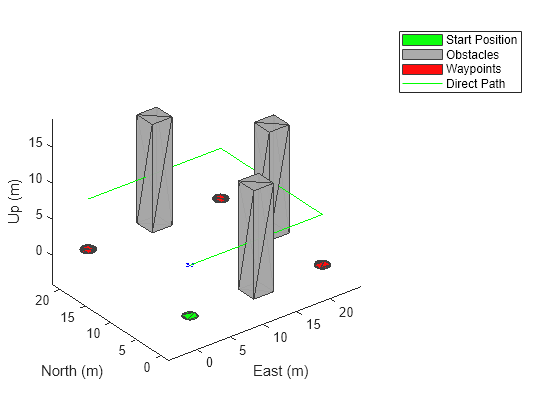
Waypoints — The set of waypoints through which the UAV is expected to fly.
Specify the waypoints for the UAV.
Waypoints = [InitialPosition; 0 20 -7; 20 20 -7; 20 0 -7];
Add markers to indicate the waypoints.
for i = 2:size(Waypoints,1)
    addMesh(Scenario,"cylinder",{[Waypoints(i,2) Waypoints(i,1) 1] [0 0.1]},[1 0 0]);
end
show3D(Scenario);
hold on
plot3([InitialPosition(1,2); Waypoints(:,2)],[InitialPosition(1,2); Waypoints(:,1)],[-InitialPosition(1,3); -Waypoints(:,3)],"-g")
legend(["Start Position","Obstacles","","","Waypoints","","","Direct Path"])
Controller and plant
The Controller and plant subsystem generates the control commands and updates the UAV state based on the lookahead point.

This subsystem includes these blocks:
Controller— This subsystem computes the control commands (roll, pitch, yaw, and thrust) to move the UAV towards the desired position. It uses multiple PID loops to implement position control.Quadrotor Plant— This Guidance Model block updates the UAV state using the control commands.Conversion — This subsystem extracts the position and orientation from the UAV state, and performs data and coordinate transforms for visualization.
Specify the controller parameters. These parameters are based on a hit-and-trial approach, and can be tuned for a smoother flight.
% Proportional Gains
Px = 6;
Py = 6;
Pz = 6.5;

% Derivative Gains
Dx = 1.5;
Dy = 1.5;
Dz = 2.5;

% Integral Gains
Ix = 0;
Iy = 0;
Iz = 0;

% Filter Coefficients
Nx = 10;
Ny = 10;
Nz = 14.4947065605712;
Specify gravity, drone mass, and sample time for the controller and plant blocks.
UAVSampleTime = 0.001;
Gravity = 9.81;
DroneMass = 0.1;
Control Panel
The switch enables or disables the updates to the lookahead point from the Obstacle Avoidance block.
The slider updates the lookahead distance used to compute the lookahead point.

At greater lookahead distances, UAV flight is faster, but has greater risk of colliding with an obstacle.
At lower values, the flight is slower, but has a lower risk of colliding with an obstacle.
Simulate Model
Configure and run the model, and observe the motion of the UAV.
The UAV flies through the waypoints while avoiding obstacles, and then the simulation stops.
Alter the lookahead distance to change the UAV speed.
Change the parameters of the Obstacle Avoidance block and note the change in the flight path.
out = sim("ObstacleAvoidanceDemo.slx");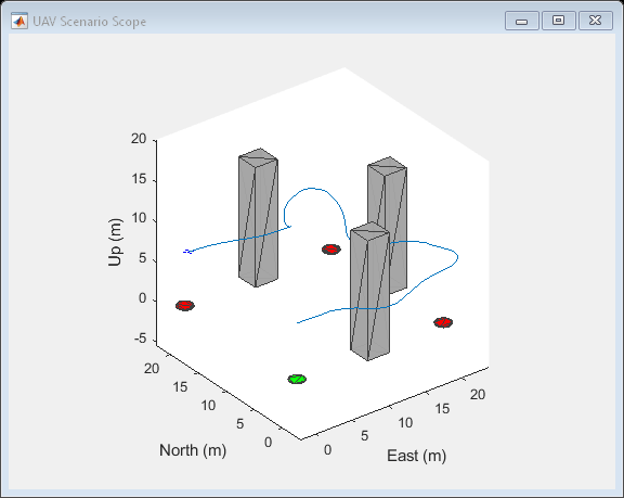
Visualize Obstacle-Free UAV Trajectory
Plot the actual UAV trajectory and the waypoints to show the effect of obstacle avoidance on the UAV flight.
hold on
points = squeeze(out.trajectoryPoints(1,:,:))';
plot3(points(:,2),points(:,1),-points(:,3),"-r");
legend(["Start Position","Obstacles","","","Waypoints","","","Direct Path","UAV Trajectory"])

See Also
Obstacle Avoidance | Guidance Model | Waypoint Follower