Create Your First Model for Connected I/O with Cube Orange+
Connected I/O allows you to interact with your flight control algorithm in Simulink® and communicate with ArduPilot® firmware running on your host computer, without deploying the algorithm. This method is fast for early-stage development and debugging, as changes in your Simulink model are reflected instantly during simulation. Using the UAV Toolbox Support Package for ArduPilot Autopilots, you can build and test models using Connected I/O before moving on to deployment or SITL simulation. For more information on Connected I/O, see Communicate with Hardware Using Connected I/O
Create a Simulink Model
Start MATLAB®. From the MATLAB toolstrip, click the Simulink button.
Click the Blank Model template.
The Simulink Editor opens.
Add a required block using the quick insert menu. For example, Timestamp block.
Double-click anywhere in the model canvas. In the quick insert menu that appears, enter
Timestamp. A list of blocks appears. Verify that the Timestamp block from the UAV Toolbox Support Package for ArduPilot Autopilots library is selected. Check the library name listed under the block name and the block description in the pane to the right of the search results.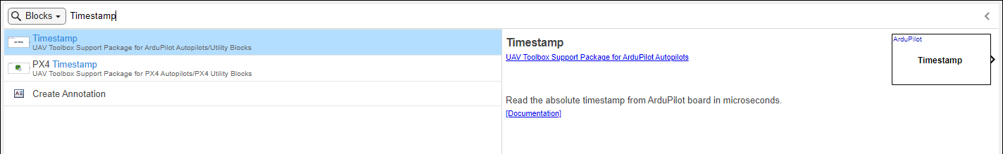
Add the Timestamp block to the model by pressing Enter.
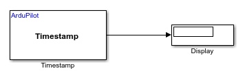
Add a Dipslay blocks and connect the blocks by creating lines between output ports and input ports. Then, save your model.
Configure Model Parameters for Cube Orange +
Set the hardware board in Simulink to ArduPilot Cube Orange + and
adjust model parameters to match the requirements of this specific autopilot. Ensure all
configuration options are correctly set for compatibility and successful deployment to
the ArduPilot Cube Orange + hardware.
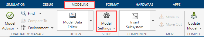
In the Simulink model, go to the Modeling > Model Settings to open Configuration Parameters dialog box.
In the Configuration Parameters dialog box, set the required parameters.
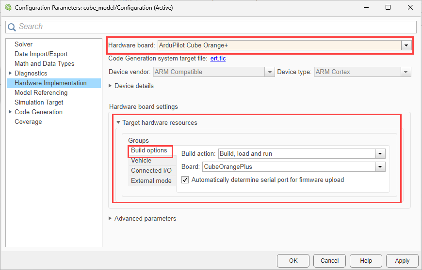
Click Hardware Implementation and select
ArduPilot Cube Orange +from the Hardware board list.In the Build options, Ensure that
Build, load and runis selected for the Build action andCubeOrangePlusis selected for the Board.Do not change any other options.
Set the options for Vehicle.
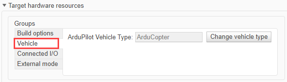
Select the required ArduPilot vehicle type.
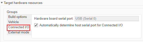
Verify the options for Connected I/O.
You can use Connected I/O simulation to communicate with the IO peripherals on the hardware. No modifications are required in this tab. For more information on Connected I/O, see Communicate with Hardware Using Connected I/O.
Click Apply and OK.
Simulate Your Simulink Model in Connected I/O
Run your Simulink model in Connected I/O mode to test and interact with your hardware in real time without full code deployment. This allows you to validate model behavior and exchange data with the hardware during simulation.
Set a value for the Simulation stop time parameter. The default value is
10.0seconds. To run the model for an indefinite period, enterinf.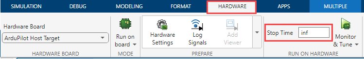
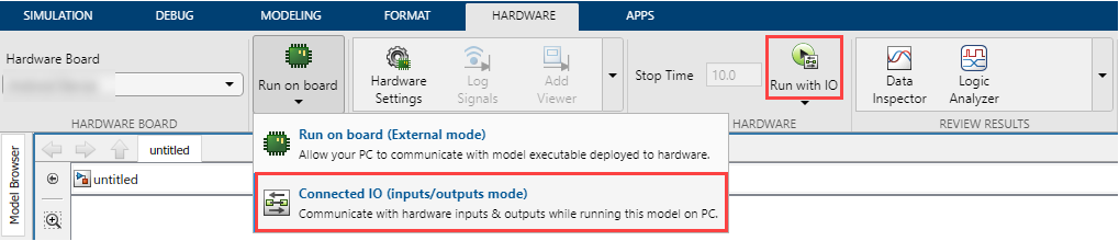
On the Hardware tab, in the in the Mode section, click Connected IO. If you see Run on board selected instead of Connected IO, click on it and choose Connected IO (inputs/outputs mode).
Run the Model
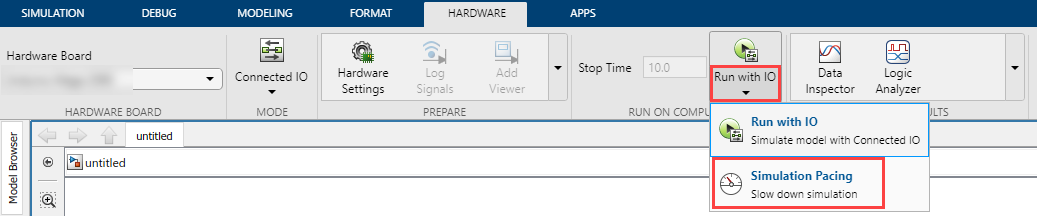
Click Run with IO.
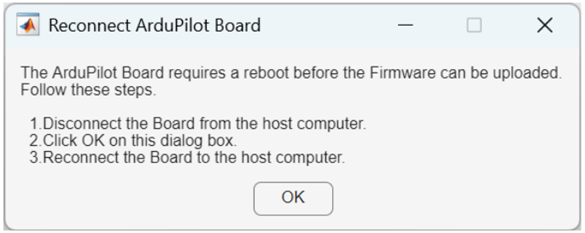
After the build completes, you will be prompted to reconnect your hardware in order to flash the generated executable. A pop-up window will be displayed with instructions.
Note
The Reconnect ArduPilot Board pop-up is only displayed when a physical ArduPilot board is selected. When using the ArduPilot Host Target, this step is skipped, as no hardware reconnection is required.
Simulink communicates with the hardware, exchanging data in real time.
Use Scope or Display blocks to observe live data.
Additionally, you can change the rate of simulation by enabling the simulation pacing. For more information, see Simulation Pacing Options (Simulink).