Configure CLB XBAR for TI C2000 Processors
R2026bThe configurable logic block (CLB) XBAR (crossbar) interconnect routes peripheral and crossbar signals into CLB tiles on Texas Instruments® C2000™ processors through eight AUXSIG channels (AUXSIG0 through AUXSIG7). You can route signals from ePWM, eCAP, INPUT XBAR, and other peripherals into CLB tile global inputs. Your digital logic can then process signals from multiple sources without additional hardware connections.
Each AUXSIG channel logically Ors selected input signals into a single output that feeds a CLB tile global input. You can assign up to 256 signals per channel for complex multi-peripheral routing.
Understand CLB XBAR Signal Routing
The CLB XBAR sits between peripheral outputs and CLB tile global inputs. Each of the eight AUXSIG channels functions as an OR gate. When you assign multiple signals to the same AUXSIG channel, the CLB tile receives the logical OR of all assigned signals as a single input.
CLB XBAR Architecture for a Single AUXSIGx Output
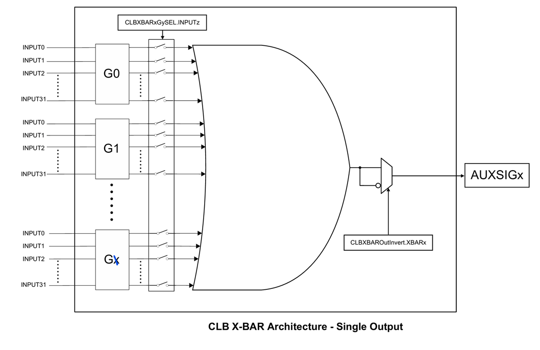
Available signal sources for CLB XBAR include:
ePWM output signals
eCAP output signals
INPUT XBAR signals (INPUTXBAR 1 through 32)
CLB output signals from other tiles (
CLBxOUT12andCLBxOUT13)Other peripheral and crossbar outputs
The 256 available signals per AUXSIG are organized internally into eight groups (G0 through G7) of 32 signals each. The configuration interface displays signals by name only, so you do not need to know which internal group a signal belongs to.
To use a CLB XBAR output in your CLB logic, configure the corresponding CLB tile input as a global input and select the appropriate AUXSIG channel. For details on CLB tile input configuration, see Configure CLB Peripheral for TI C2000 Processors.
Configure CLB XBAR Signal Assignments
To access CLB XBAR settings, in your Simulink® model, on the Modeling tab, click Model Settings. In the Configuration Parameters dialog box, click Hardware Implementation and select the CLB XBAR tab under Target Hardware Resources.

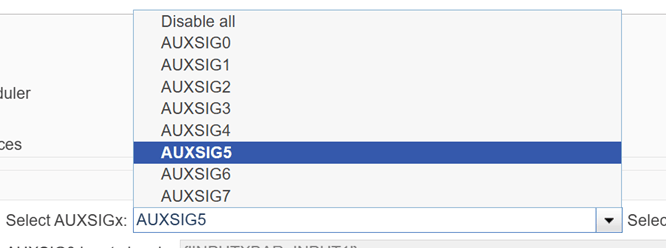
Select AUXSIG Channel
In the AUXSIG parameter, select the AUXSIG channel (AUXSIG0 through AUXSIG7) that you want to configure. Each AUXSIG channel corresponds to one global input path available to all CLB tiles.
Add Signals to AUXSIG Channel
To route peripheral signals to the selected AUXSIG channel:
From the available signals list, select the signal you want to route. The list displays signal names from all available peripherals and crossbars.
Add the signal to the AUXSIG channel. The configured signal appears in the cell array display for the selected AUXSIG.
To combine multiple signals through the OR gate, repeat the selection for each additional signal.

The CLB XBAR logically ORs all signals assigned to the same AUXSIG channel. The CLB tile receives this combined signal at its global input when you select this AUXSIG as the input source.
Tip
If you need to process individual peripheral signals independently in your CLB logic, assign each signal to a separate AUXSIG channel and route each to a different tile input. Reserve the OR-aggregation capability for cases where you want a single CLB input to respond to any one of several trigger sources.
Remove Signals from AUXSIG Channel
To remove a specific signal:
In the AUXSIG parameter, select the channel containing the signal.
Select the signal to remove from the configured signals list.
Click Remove.
To clear all signals from a channel at once, select the AUXSIG channel and click Remove All. The channel resets to an reconfigured state with no routed signals.
Connect CLB XBAR to CLB Tile Inputs
CLB XBAR and CLB tile configuration work together. After you configure AUXSIG channels in the CLB XBAR tab, connect them to your CLB tiles:
In the Configuration Parameters dialog box, select the CLB tab.
For the target tile, in the IN# MUX selection parameter, select Global.
In the Input parameter, select the AUXSIG channel (for example, AUXSIG0) that you configured with your desired signals.
This completes the signal path from peripheral outputs through CLB XBAR into the CLB tile, where the SysCfg-defined logic processes the input.
Multicore Signal Routing
On multicore F29x devices, CPU1 owns the CLB XBAR register configuration. To modify CLB XBAR routing, other CPUs (CPU2, CPU3) must issue IPC (Inter-Processor Communication) commands through CPU1.
The generated code handles this when you configure CLB XBAR in a multicore model.
The c29h85xBoard_Realtime_Support.c source file enables the CLB
peripheral clock, assigns CPU ownership, and configures IPC access permissions for
CLB XBAR registers.
Design Considerations
When planning your CLB XBAR configuration, consider these factors:
| Consideration | Guidance |
|---|---|
| Signal independence | To process signals independently, assign each to a separate AUXSIG channel |
| Signal timing | The OR operation is combinational. Signal timing depends on the source peripheral and input synchronization settings in the CLB tile |
| Resource sharing | AUXSIG channels are shared across all CLB tiles. Verify that your AUXSIG allocation does not conflict with other tiles that use the same channel |
| Migration from F28x | The F29x CLB XBAR uses a simplified interface that hides internal group numbers. If you are migrating from F28x, select signals by name rather than by group and index |
Limitations
Each AUXSIG channel supports a maximum of 256 signals. Some signal positions in the internal groups are reserved and not selectable.
The blockset currently supports the F29H85x processor. The blockset does not yet support the F28P58x processor.
SysCfg integration with F29x requires Code Composer Studio (CCS) v20 or later.

