Parameter Tuning and Signal Logging with Serial External Mode
This example shows how to perform parameter tuning and data logging with a Simulink® model running in External mode on VEX® EDR V5 Robot Brain.
Required Hardware:
VEX EDR V5 Robot Brain
USB A to Micro Cable
Model
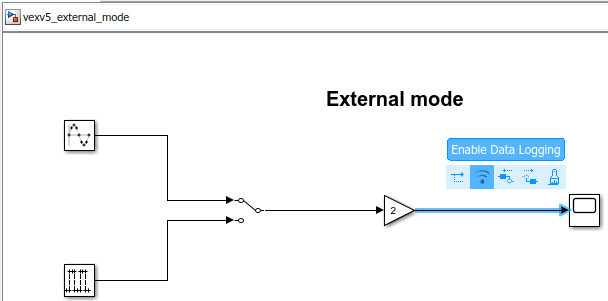
The following figure shows the example model.

Description
In this example, you will learn how to run a Simulink model, tune the parameters, and log data in External mode.
Configure the Hardware and Model for External Mode
Set up the hardware
Connect the VEX EDR V5 Robot Brain to the computer using a USB A to Micro Cable. The connection should automatically enable serial connection between the target and the host computer.
Set up the model
1. Open the vexv5_external_mode Example Model.
2. Mark the signal, which you will be monitoring, for logging. To do this, open the context menu of the signal that connects the Gain block to the Scope block, and select Enable Data Logging.
This model has already been configured for External mode. To set up External mode for a new model, follow the steps below.
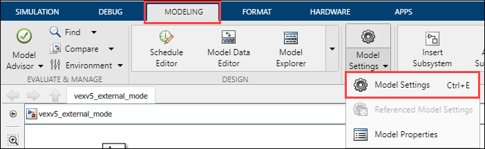
3. Go to Modeling tab and select Model Settings or Ctrl+E to open Model Configuration Parameters.
4. Navigate to the Hardware Implementation pane and select the Hardware board as VEX V5 Robot Brain.
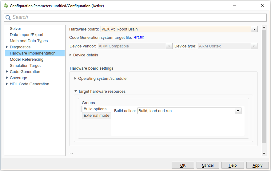
Click Apply and then OK to close the Model Configuration Parameters dialog box.
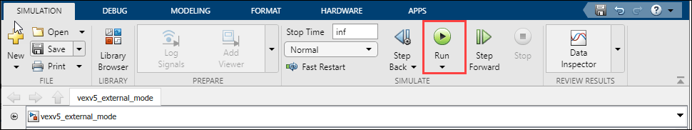
5. Go to Hardware tab and select Monitor & Tune for external mode and specify a desired value for the stop time. Specify the stop time as 'inf' to run the model continuously on the target hardware.

Run the model in External mode
When running in External mode, the host computer communicates with the target to log data and tune parameters. To run the vexv5_external_mode Example Model in External mode:
1. Press the Run button on the Simulink tab. Simulink generates the code, loads the executable and connects to the target. View the Diagnostic Viewer to track progress.
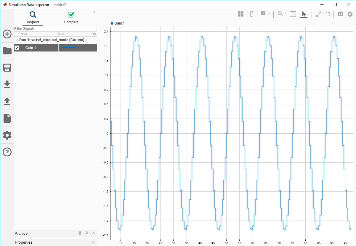
2. While the model is running in External mode, click the Simulation Data Inspector button from the Simulink tab.

3. In the Simulation Data Inspector dialog box, monitor the output signal from the Gain block.
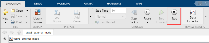
4. Press the Stop button on the Simulink tab to terminate the External mode simulation.
Parameter Tuning and Data Logging
Parameter Tuning
Simulink External mode provides parameter tuning while the generated executable is running on the target hardware. When the parameter values are changed in the Simulink model, the modified values are communicated to the target hardware immediately.
To tune parameters in External mode:
1. Run the model in External mode.
2. While the model is running, double click on the Gain block and change the Gain value. View the result in the Simulation Data Inspector. The amplitude of the sine waveform changes accordingly.
3. To switch the input source, double click on the Manual Switch block. View the result in the Simulation Data Inspector. If the Verbose is selected in the Model Configuration Parameters > Hardware Implementation > Target Hardware Resources > External mode, the status of the parameter change is displayed on the MATLAB® Command Window.
4. Stop External mode simulation.
Data Logging
To log External mode data to a MAT file, you can either use the Scope or the To Workspace block. Simulink supports multiple data logging schemes. The below steps explain, the default, manually triggered scheme.
1. Click on the Data Archiving button of the External Mode Control Panel (Code > External Mode Control Panel ). Check the Enable Archiving option. Use the Directory parameters to specify the destination of your log file, and File to specify the name of your log file.
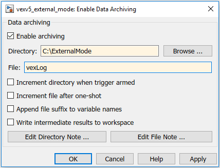
In Data Archiving, new data sets are saved in new MAT files (log files). Each data set is of the size of the Duration (Code > External Mode Control Panel > Signal & Triggering > Duration). Duration specifies the minimum contiguous data to be collected by External mode.
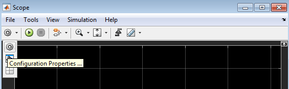
2. Open the Scope connected to the Gain block and click on the Configuration Properties button.
3. Navigate to the Logging tab and check the Log data to workspace option. Specify a name in Variable name. The logged data is saved in this variable. To save the corresponding time instants along with the logged data, select Save Format as Structure With Time.

Note: If you do not check the Log data to workspace option, empty MAT-files will be created.
4. Run the model in External mode by clicking on the Run button. Navigate to the folder specified for saving the logged data(path mentioned in step 1). Several MAT files will be created, each containing a structure with 25 contiguous data samples. You can change the size of the contiguous data samples by changing Duration (Code > External Mode Control Panel > Signal & Triggering > Duration).
5. Press the Stop button in the Simulink Editor to terminate the External mode simulation.
Limitations
1. There might be problem cases in which External mode on the VEX EDR V5 Robot Brain does not start. In such cases, the serial Port (COM Port) may not have been closed properly. To overcome this, connect and disconnect the USB A to Micro Cable.
2. Increasing the Duration allows MAT file logging with large contiguous data sets. A high value of Duration may result in Not enough memory on the target to process the packet warning, and consequently cause no data to be logged. If you face this warning, either decrease the number of scopes or decrease the Duration (Code > External Mode Control Panel > Signal & Triggering > Duration).
Select a Web Site
Choose a web site to get translated content where available and see local events and offers. Based on your location, we recommend that you select: United States.
You can also select a web site from the following list
Americas
- América Latina (Español)
- Canada (English)
- United States (English)
Europe
- Belgium (English)
- Denmark (English)
- Deutschland (Deutsch)
- España (Español)
- Finland (English)
- France (Français)
- Ireland (English)
- Italia (Italiano)
- Luxembourg (English)
- Netherlands (English)
- Norway (English)
- Österreich (Deutsch)
- Portugal (English)
- Sweden (English)
- Switzerland
- United Kingdom (English)