Communicating with a Parrot Minidrone Using TCP/IP and UDP
This example shows how to use the TCP/IP and UDP communication blocks in the Simulink® Support Package for Parrot® Minidrones. The blocks are used to control the motor speed of the drone and visualize the accelerometer sensor data from the drone.
Introduction
The Simulink Support Package for Parrot Minidrones provides a library with TCP/IP and UDP communication blocks, which enable you to establish TCP/IP and UDP connections between the Parrot minidrone and the host computer.
To view the TCP/IP and UDP communication blocks:
1. Enter slLibraryBrowser at the MATLAB® prompt.
2. In the Simulink Library Browser, navigate to Simulink Support Package for Parrot Minidrones. You can see the TCP/IP Send and Receive blocks and the UDP Send and Receive blocks.

In this example, you will learn how to use the TCP/IP and UDP blocks to:
Control the speed of propellers connected to the motors on the Parrot minidrone using TCP/IP connection
Send accelerometer sensor data from the drone to the host computer using UDP connection
Use the Scope in the host model to visualize the variation of acceleration.
The Simulink models used in this example are:
Target Communication Model(CommunicatingParrotMinidroneTCPUDP) - This model is run on the Parrot Minidrone.
Host Communication Model(CommunicatingParrotMinidroneTCPUDPHost) - This model is run on the host computer.
Prerequisites
If you are new to Simulink, complete the Interactive Simulink Tutorial.
To setup and run Simulink model on a Parrot minidrone, follow the example described in Spin the Motors of a Parrot Minidrone Without Flying the Drone.
Required Hardware
To run this example, you will need the following hardware:
Parrot Rolling Spider Or Parrot Mambo minidrone with a fully charged battery and propellers connected to the motors
Micro USB type-B cable
Bluetooth® Low energy (BLE) 4.0 support on the host computer
Task 1 - Configure and Deploy the Simulink Model on Parrot Minidrone
This task shows how to configure the input and output ports of TCP/IP and UDP blocks in a Simulink model and then deploy the model on the Parrot minidrone.
1. Open the parrot_communication Model.

2. Open the "Flight_Control_System" subsystem. The output port Data of the TCP/IP Receive block is connected to input ports 1 and 3 of the Concatenate block. The Concatenate input ports correspond to the RPM values assigned to the motors.
3. Double click on the TCP/IP Receive block. The Local IP port value is set to 25000, which matches the remote port on the TCP Send block in the Host Communication Model(CommunicatingParrotMinidroneTCPUDPHost). The Data type is set to double and Data size is set to 1. Ensure that the Data type and Data size parameters in the host model are set to the same values as the parameters in the target model.
The Connection mode of TCP/IP Receive block can be Server or Client. For this model, the Connection mode is set to Server. This is because, in the host Simulink model, we are using a TCP Send block to serve as a client. Click OK to save and close the block.
4. Double-click on the UDP Send block. The Remote IP address is the IP address of the Bluetooth interface on the host computer. Use the default address, 192.168.3.2. The Remote IP port parameter is set to 29000 to match the local port in the UDP Receive block in the host Simulink model. Click OK to save and close the block.
5. On the toolbar of the Simulink model window, click the Deploy to Hardware icon.
6. If you have selected the Launch Parrot Flight Control Interface automatically after build option in the Configuration Parameters dialog box (Hardware Implementation pane > Target Hardware Resources > Build Options), the Parrot Flight Control UI opens automatically after the build goes through successfully.
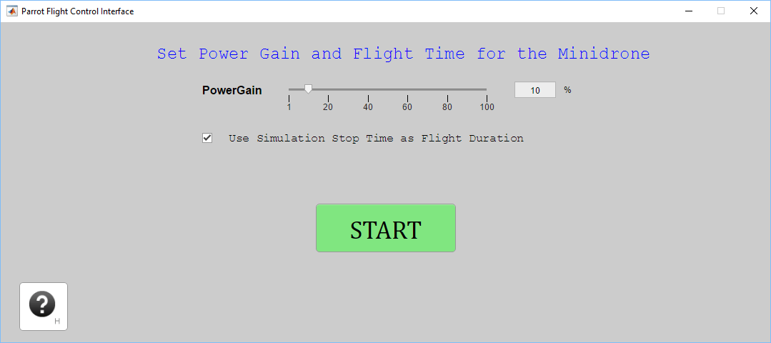
You can also open the Parrot Flight Control Interface from the command line.
>> Parrot_FlightInterface
To know more about Parrot Flight Interface, go to this section.
Task 2 - Run Communication Model on the Host Computer
In this task, you will configure and run a Simulink model on the host computer to communicate with the target model deployed on the drone.
The host Simulink model performs the following functions:
Starts motors 1 and 3 on the drone
Sends varying motor speed inputs using a Knob block to the target model running on the drone
Receives the sensor data sent by the target model
Note: The host Simulink model uses TCP/IP blocks and UDP blocks from the Instrument Control Toolbox in the Simulink Library Browser. The model uses TCP/IP to send the commands that starts the motors and changes the speed of motors, and uses UDP to receive the data from the accelerometer sensor on the drone.
1. Open the parrot_communication_host model.
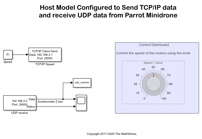
2. Double-click on the UDP Receive block. This block is configured to receive UDP packets sent by the model running on the Parrot minidrone. The Local port is set to 29000, and the output Data type is set to single to match the sensor value type. Click OK to save and close the block.
3. Double-click on the TCP/IP Send block. This block is configured to transmit the packets on port 25000 to 192.168.3.5, which is the IP address of the Parrot Rolling Spider minidrone. If you are using a Parrot Mambo minidrone, change the address to 192.168.3.1. Click OK to save and close the block.
4. On the Flight Control Interface (launched in Task 2), click START. The deployed target model on the drone starts sending UDP packets to port 29000 of the host computer. The drone is also prepared to receive TCP/IP data at port 25000.
You can relaunch the interface by executing Parrot_FlightInterface at the MATLAB command window.
5. On the toolbar of the host model Simulink window, click the Run icon to simulate the model. You will observe propellers connected to motors 1 and 3 begin to spin.
6. Change the knob position in the host model to control the speed of the motors. Notice the change in speed of the propellers after some delay.
NOTE :
The Simulink model on the host does not run in real time. Hence, we might notice some delay in the speed change of the propellers. You can use Set Pace block from Aerospace Blockset/Animation Support Utilities or real-time block from this MATLAB File Exchange page.
7. Double-click on the Scope block in the host model to see the variation in acceleration sensed by the Parrot Minidrone in the Z direction (the Z value is positive in the downward direction). Change the position of the drone from the ground level (raise or lower the drone). Double-click on the Scope block to observe the change in the sensor value.
Other Things to Try with TCP/IP and UDP Blocks in Simulink Support Package for Parrot Minidrones
Create and run a model that increases the motor speed when the drone is tilted forward, and reduces the motor speed when the drone is tilted backward. Tip: Use the accelerometer data from the input port Sensors to determine the tilt angle.
Select a Web Site
Choose a web site to get translated content where available and see local events and offers. Based on your location, we recommend that you select: United States.
You can also select a web site from the following list
Americas
- América Latina (Español)
- Canada (English)
- United States (English)
Europe
- Belgium (English)
- Denmark (English)
- Deutschland (Deutsch)
- España (Español)
- Finland (English)
- France (Français)
- Ireland (English)
- Italia (Italiano)
- Luxembourg (English)
- Netherlands (English)
- Norway (English)
- Österreich (Deutsch)
- Portugal (English)
- Sweden (English)
- Switzerland
- United Kingdom (English)