Represent Multiple Paths by Using Connective Junctions
The label format for a transition segment entering a junction is the same as for transitions entering states, as shown in this image:
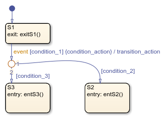
In this image, the execution order is:
When an event occurs, the chart checks state
S1for an outgoing transition that matches the specified event.If the chart finds a transition with a matching event, the chart evaluates the transition.
If
condition_1evaluates to true, the chart executes the condition actioncondition_action.The chart checks the outgoing transitions from the junction for a valid transition. Because
condition_2is true, a valid state-to-state transition exists fromS1toS2.The state
S1exit actions execute and complete.State
S1becomes inactive.The transition action
transition_actionexecutes and completes.The completed state-to-state transition from
S1toS2occurs.State
S2becomes active.The state
S2entry action executes and completes.
If-Then-Else Decision Construct
This image shows the behavior of an if-then-else decision
construct.

Initially, the chart is asleep. State A is active and condition
[C_two] is true. Event E_one occurs and
wakes the chart, which processes the event from the root through the
hierarchy:
The chart root checks to see if there is a valid transition as a result of
E_one.A valid transition segment from state
Ato the connective junction exists. The chart evaluates the transition segments according to their labeled order. The first transition segment, condition [C_one], is not valid. The next transition segment, condition [C_two], is valid. The complete transition from stateAto stateCis valid.The state
Aexit actionexitA()executes and completes.State
Abecomes inactive.State
Cbecomes active.The state
Centry actionentC()executes and completes.The chart goes to sleep.
Self-Loop Transition
This image shows the behavior of a self-loop transition that uses a connective junction.

Initially, the chart is asleep. State A is active and condition
[C_one] is false. Event E_one occurs and
wakes the chart, which processes the event from the root down through the
hierarchy:
The chart root checks if there is a valid transition as a result of
E_one. A valid transition segment from stateAto the connective junction exists. The chart evaluates the transition segments according to their labeled order. Because the condition [C_one] is not valid, the complete transition from stateAto stateBis not valid. The transition segment from the connective junction back to stateAis valid.The state
Aexit actionsexitA()executes and completes.State
Abecomes inactive.The transition action
A_twoexecutes and completes.State
Abecomes active.The state
Aentry actionsentA()executes and completes.The chart goes to sleep.
For-Loop Construct
This example shows the behavior of a for-loop that uses a
connective junction.

Initially, the chart is asleep. State A is active. Event
E_one occurs and awakens the chart, which processes the event
from the root down through the hierarchy:
The chart root checks if there is a valid transition as a result of
E_one. There is a valid transition segment from stateAto the connective junction. The transition segment condition action,i = 0, executes and completes. Of the two transition segments that leave the connective junction, the chart evaluates the transition segment that is a self-loop back to the connective junction next. That segment takes priority in evaluation because it has a condition, whereas the other segment is unlabeled. This evaluation behavior reflects the ordering of outgoing transitions in the chart.The condition
[i < 10]evaluates as true. The condition actioni++and the call tofunc1execute and complete until the condition becomes false. Because a connective junction is not a final destination, the transition destination is still unknown.The unconditional segment to state
Bis now valid. The complete transition from stateAto stateBis valid.The state
Aexit actionexitA()executes and completes.State
Abecomes inactive.State
Bbecomes active.The state
Bentry actionentB()executes and completes.The chart goes back to sleep.
Flow Chart Notation
This image shows the behavior of a Stateflow® chart that uses flow chart notation.
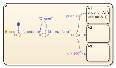
Initially, the chart is asleep. State A.A1 is active and
condition [C_one()] is true. Event E_one
occurs and wakes the chart, which processes the event from the root through the
hierarchy:
The chart root checks if there is a valid transition as a result of
E_one. There is no valid transition.State
Achecks itself for valid transitions and detects a valid inner transition to a connective junction.The chart evaluates next possible segments of the transition. Only one outgoing transition exists, and it has a condition action. The condition action executes and completes.
The chart evaluates the next possible segments. Two outgoing transitions exist: a conditional self-loop transition and an unconditional transition segment. Because of the assigned evaluation order, the conditional transition segment takes precedence. Because the condition
[C_one()]is true, the chart takes the self-loop transition. Because a final transition destination has not been reached, this self-loop continues until[C_one()]is false.Assume that after five iterations,
[C_one()]is false.The chart evaluates the next possible transition segment. This transition is an unconditional transition segment with a condition action. The chart takes the transition segment and the condition action,
{d=my_func()}, executes and completes. The returned value ofdis 84.The chart evaluates the next possible transition segment. Three outgoing transition segments exist: two conditional and one unconditional. Because of the assigned evaluation order, the segment with the condition
[d < 100]evaluates first based on the geometry of the two outgoing conditional transition segments. Because the returned value ofdis 84, the condition[d < 100]is true and this transition to the destination stateA.A1is valid.The state
A.A1exit actionexitA1()executes and completes.State
A.A1becomes inactive.State
A.A1becomes active.The state
A.A1entry actionentA1()executes and completes.The chart goes to sleep.
Transition from a Common Source to Multiple Destinations
This image shows the behavior of transitions from a common source to multiple conditional destinations using a connective junction.

Initially, the chart is asleep. State A is active. Event
E_two occurs and wakes the chart, which processes the event
from the root through the hierarchy:
The chart root checks to see if there is a valid transition as a result of
E_two. A valid transition segment exists from stateAto the connective junction. The chart evaluates the segments according to their assigned order. The first transition segment,E_one, is not valid. The next transition segment,E_two, is valid. The complete transition from stateAto stateCis valid.The state
Aexit actionexitA()executes and completes.State
Ais marked inactive.State
Cis marked active.The state
Centry actionentC()executes and completes.The chart goes to sleep.
Resolve Equally Valid Transition Paths
A chart contains conflicting transitions when it has two equally valid paths from the same source. In the case of a conflict, the chart evaluates the equally valid transitions based on the order you specify for each transition.
For example, this chart has two equally valid transition paths.
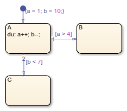
The default transition sets the value of data a to 1 and the
value of data b to 10. The during action of
state A increments a and decrements
b during each time step. The transition from state
A to state B is valid if the condition
[a > 4] is true. The transition from state
A to state C is valid if the condition
[b < 7] is true. During simulation, there is a time step
where state A is active and both conditions are true. This causes
a transition conflict.
By default, the chart executes conditions in the order you created them. However,
you can also manually change the execution order. For example, if you right-click
the transition from state A to state C and
select Execution Order > 1 from the context menu, the chart evaluates that transition first. In
this case, the transition from state A to state
C occurs.
Transition from Multiple Sources to a Common Destination
This image shows the behavior of transitions from multiple sources to a single destination using a connective junction.

Initially, the chart is asleep. State A is active. Event
E_one occurs and wakes the chart, which processes the event
from the root through the hierarchy:
The chart root checks if there is a valid transition as a result of
E_one. A valid transition segment exists from stateAto the connective junction and from the junction to stateC.The state
Aexit actionexitA()executes and completes.State
Abecomes inactive.State
Cbecomes active.The state
Centry actionentC()executes and completes.The chart goes to sleep.
Transition from a Source to a Destination Based on a Common Event
This image shows the behavior of transitions from multiple sources to a single destination using a connective junction. The transition segment located after the junction contains an event.

Initially, the chart is asleep. State B is active. Event
E_one occurs and wakes the chart, which processes the event
from the root through the hierarchy:
The chart root checks if there is a valid transition as a result of
E_one. A valid transition segment exists from stateBto the connective junction and from the junction to state C.The state
Bexit actionexitB()executes and completes.State
Bbecomes inactive.State
Cbecomes active.The state
Centry actionentC()executes and completes.The chart goes to sleep.
Backtrack in Flow Charts
This image shows the behavior of transitions with junctions that force backtracking behavior in flow charts.
![]()
Initially, state A is active, conditions c1,
c2, and c3 are true, and condition
c4 is false.
The chart root checks if there is a valid transition from state
A.Condition
c1, which connects stateAto a connective junction, is valid.Condition
c1is true and actiona1executes.Condition
c3is true and actiona3executes.Condition
c4is not true and the chart backtracks to stateA.The chart root checks to see if there is another valid transition from state
A.Condition
c2, which connects stateAto a connective junction, is valid.Condition
c2is true and actiona2executes.Condition
c3is true and actiona3executes.Condition
c4is not true and the chart backtracks to stateA.The chart goes to sleep.
In the previous image, the chart executes both actions a1 and
a2 and executes a3 twice. To resolve this
problem, consider adding unconditional transitions to terminating junctions.
![]()
The terminating junctions allow flow to end if either c3 or
c4 is not true. This design leaves state A active without
executing unnecessary actions.
Additional Examples of Unintended Backtrack
Open this model to see additional examples of unintended backtracking in flow charts.