Detect and Isolate Faults in an Aircraft Elevator Control System
This example shows how to design a fault detection, isolation, and recovery (FDIR) application for a pair of aircraft elevators by using Stateflow® charts.

A typical aircraft has two elevators, one on each side of the fuselage, attached to the horizontal tailplanes. To enhance the safety of the aircraft, the elevator control system contains these redundant parts:
Two actuators per elevator: A primary actuator located on the outer edge, and a backup actuator located on the inner edge. Only one actuator is active in each elevator at a time.
Three hydraulic circuits that drive the actuators. Each outer actuator has a dedicated hydraulic circuit. The inner actuators share a hydraulic circuit.
Three sensors on each actuator and hydraulic circuit. The actuator sensors measure position, while the hydraulic circuit sensors measure pressure.
A primary flight control computer (PFCC) that contains two primary flight control units (PFCU). One PCFU controls the inner actuators and the other controls the outer actuators. The computer activates or deactivates the PFCUs in response to faults.
Four remote electronic units (REU), one for each actuator. The REUs translate the movement of the control wheel into instructions for the actuators, and translate the sensor readings from the actuators and hydraulic circuits into conditioned data for the PFCUs.

If the aircraft is flying perfectly level, then the actuator position maintains a constant value. The fault detection system registers a failure in an actuator if:
The position of the actuator increases or decreases by 10 cm from this zero point.
The actuator position changes at least 20 cm in 10 milliseconds.
The fault detection system registers a fault in the hydraulic circuits if:
The pressure in the hydraulic circuit is not between 500 kPa and 2 MPa.
The pressure changes at least 100 kPa in 0.01 seconds.
Model Altitude Control
The sf_aircraft model uses several charts and subsystems to represent the control and movement of the aircraft.
At the top level of the model, the Pilot Signal Editor block represents a pilot pushing or pulling the control wheel to change the altitude of the plane. The Pilot block outputs the raw control wheel data to the Primary Flight Control Computer subsystem, which sends the data to the Remote Electronic Units subsystem.
The Remote Electronic Units subsystem contains four referenced subsystems that each represent the REU for the corresponding actuator.

Each REU subsystem contains the charts Control Law and Sensor Screening. The Control Law chart converts the raw control wheel data into movement instructions for the connected actuator.

The Control Law chart uses one of two Simulink based states, depending on whether the REU is connected to an inner or outer actuator:
The REUs for the outer actuators use a proportional-integrative-derivative (PID) control law to smooth the raw control wheel data.
The REUs for the inner actuators use a proportional control law, which does not smooth the raw control wheel data.

The Remote Electronic Units subsystems sends the instructions to the Plant subsystem, which simulates the movement of the actuators. The Plant subsystem sends the raw sensor data from the actuators and hydraulic circuits back to the Remote Electronic Units subsystem.
Model Fault Detection, Isolation, and Recovery System
The sf_aircraft model uses several charts and subsystems to process sensor readings, detect faults, and respond to faults.
Detect Faults
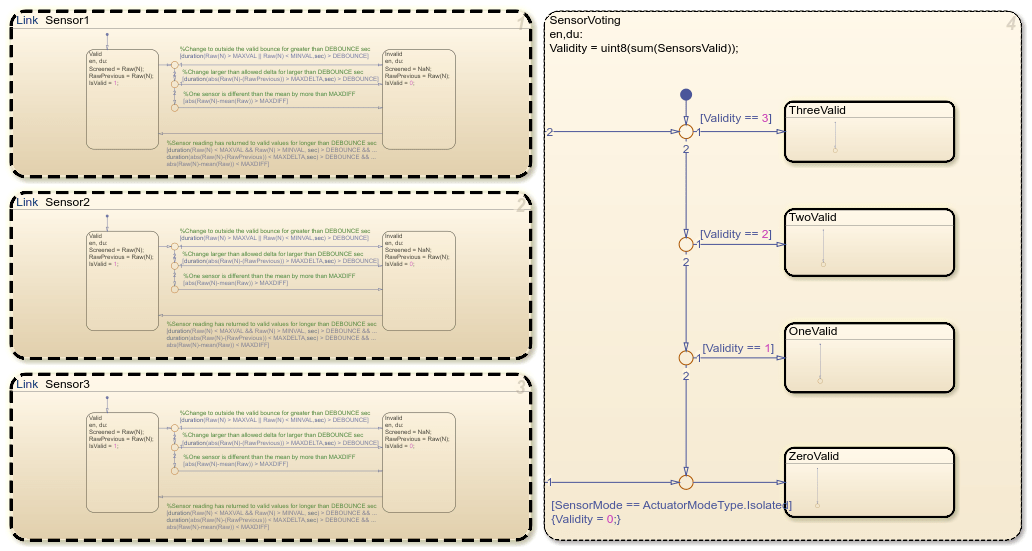
In the system for each REU, the Sensor Screening chart has linked library charts PositionSensorScreen and HydraulicSensorScreen.

Each sensor screening chart performs these actions:
Check the three associated actuator position or hydraulic pressure readings for faults.
Condition the readings into a single data value.
If one or two readings contain a fault, the screening chart omits the faulty readings. If all three sensors contain a fault, the screening chart instead registers a fault. Actuator position faults register for the associated actuator. Hydraulic pressure faults register for any actuators connected to the hydraulic circuit.
The screening charts send the conditioned sensor data and registered faults up through the model hierarchy, to the Remote Electronic Units subsystem. The subsystem sends this information to the Primary Flight Control Computer subsystem.
Isolate and Recover from Faults
The Primary Flight Control Computer subsystem uses the Fault Control Algorithm truth table to determine which PFCU to activate or deactivate in response to faults.
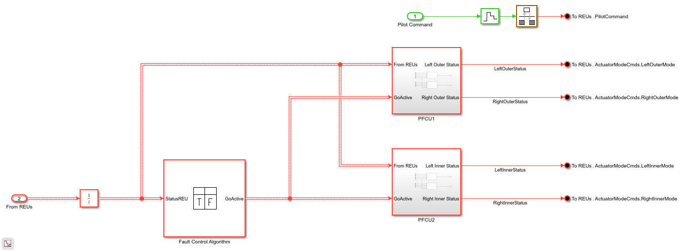
If the truth table detects a fault in an actuator in the active PFCU, the PFCC switches to the opposite PFCU.
If the truth table detects a fault in actuators in both PFCUs, the PFCC takes one of these actions:
If actuators on opposite sides experience faults, the PFCC keeps the plane operable by activating both PFCUs. For example, if the left inner and right outer actuators have a fault, both PFCUs remain active.
If actuators on the same side experience faults, the PFCC deactivates both PFCUs. For example, if the left inner and left outer actuators fail, neither PFCU remains active.
The truth table sends the instructions to the subsystems PFCU1 and PFCU2, which respectively control the outer and inner actuators. The subsystems have two charts, one for each actuator. The actuator charts link from a library chart located in the file sf_aircraft_lib.slx.
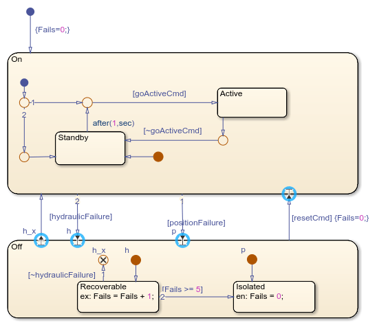
In the actuator charts, the On state represents an actuator without faults. The chart moves to the child state Active when the associated PFCU activates, and moves to the child state Standby when the associated PFCU deactivates.
When the actuator experiences a fault, the chart moves to the Off state. The chart enters the child state Recoverable if the actuator experiences:
Only a hydraulic pressure failure.
A hydraulic pressure failure followed by an actuator position failure.
The chart enters the child state Isolated if the actuator experiences:
Only an actuator position failure.
Five or more recoverable failures.
When the fault resolves, actuators in the Recoverable state return to the On state. Actuators in the Isolated state remain inactive for the rest of the simulation, unless you manually reset the fault detection system.
Observe Fault Management by Injecting and Resetting Faults
You can observe how the fault management system operates by injecting faults, withdrawing faults, or resetting isolated actuators.
Inject Faults
To introduce actuator and hydraulic circuit faults during simulation, in the top-level model, use the sliders in the boxes Injection Position Sensor Failures and Inject Hydraulic Pressure Failures. When you inject a position sensor failure, the model rapidly changes the specified actuator position. When you inject a hydraulic pressure failure, the model rapidly decreases the specified hydraulic circuit pressure.

For example, to inject a fault in Hydraulic Circuit 1, which is connected to the left outer actuator:
Return to the top level of the model.
In the Inject Hydraulic Pressure Failures box, slide H1 to the right by clicking the right edge of the slider.
When you inject the fault, the model responds to the failure.
In the
Remote Electronic Unitssubsystem, in theLeftOutersubsystem, theSensor Screeningchart registers the fault.The
Primary Flight Control Computersubsystem receives the fault. The subsystem deactivates the PFCU for the outer actuators and activates the PFCU for the inner actuators.The inner actuators activate.
The left outer actuator moves to recoverable.
The right outer actuator moves to standby.
To bring Hydraulic Circuit 1 back online, slide H1 to the left. The model removes the failure.
The left outer actuator moves to standby.
The inner actuators remain active.
The model can now reactivate the outer actuators if the inner actuators fail.
Reset Isolated Actuators
To reset isolated actuators, click the Reset button. The button activates a command that:
Instructs each actuator chart to reset the failure counter to
0and transition to theOnstateActivates the PFCU connected to the outer actuators
The button does not reset the failure injection sliders.
References
Pieter J. Mosterman and Jason Ghidella, "Model Reuse for the Training of Fault Scenarios in Aerospace," in Proceedings of the AIAA® Modeling and Simulation Technologies Conference, CD-ROM, paper 2004-4931, August 16 - 19, 2004, Rhode Island Convention Center, Providence, RI.
Jason R. Ghidella and Pieter J. Mosterman, "Applying Model-Based Design to a Fault Detection, Isolation, and Recovery System," in Military Embedded Systems, Summer, 2006.